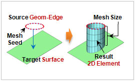
Select
the 1D element, element side or seeded line (edge) to
be extruded and set the projection target (target surface)
and direction. The element size can be directly entered
or defined by the number of divisions on the distance
to the projection. The original element used in extrude
can be deleted/moved/copied. For move, the used element
is moved to the end of the extruded element.
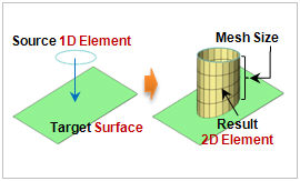 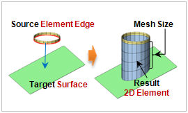
<1D element->2D
Project extrude> <Element
edge->2D Project extrude>
<Geometry edge->2D Project
extrude>
Project Target
Select
an existing surface of a geometry shape or an element
boundary surface as the projection target (target surface).
Or, select 3 arbitrary points that pass the target surface
using the [Tree Points Plane] function.
Projection Direction
Set
the projection direction using the axis direction on the
GCS or the direction of an arbitrary vector that connects
the start and end points. Use the [Shortest Path Line]
to automatically set the shortest distance direction between
the node and projection target (target surface) in the
normal direction. |