Select
the node where the displacement will be applied and set
the size and direction. The target selection method and
size/direction settings are as follows:
[Object]

The
applied displacement is defined on the node, but the selection
target can also be set as a geometry shape (edge, surface
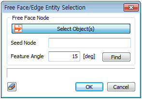
etc.) or using auto-select free face nodes. For an edge
or surface, the selected shape must have been used for
element creation and the displacement is applied to all
nodes in the specified direction/size. For free face nodes,
select a free face node and all points that make contact
with the node-containing element at an angle smaller than
the specified angle (feature angle) are automatically
selected.

[Components]
Input
the displacement size according to the set direction.
A positive (+) value applies the displacement in the set
direction and a negative (-) value applies the displacement
in the opposite direction to the set direction. The size
change with respect to the coordinate value increase in
the GCS can be defined using a reference function. Here,
the input value is multiplied by the function value for
application. |


