Display
the usable Mesh sets, Boundary sets and Load sets.
Select the desired data and drag it to the Set
assignment rule, or drag the Mesh set, Boundary
set and Load set to the activation state.
Be aware that the display
format of each set is completely different from
the workstree. Here, all mesh sets are displayed
as individual mesh sets, ignoring the relationship
between mesh sets and sub-mesh sets in the workstree.
Also, the upper most display name is the mesh
set name without the postfix. Expanding one step
displays the mesh set name with the postfix.
Refer to the following
example.

<Element,
Boundary, Load display format>
Set
Assignment Rule
Specify
the construction stage set used to define the
construction stage and specify the assignment
rule.

The type
of set on which the construction stage will be
defined. The user can select between Mesh set,
Boundary set or Load set.
Specify
the name without the serial number of the set
on which the construction stage will be defined.
For example,
if a Mesh set is specified from ‘Final Core #001’
to ‘Final Core #012’, select the Set name prefix
as ‘‘Final Core #’.
Select
whether to Add or Remove a selected set. A is
displayed in green and R is displayed in yellow.
Specify
the set number of the selected set that is used
first in the construction stage.
For example,
if a Mesh set specified from ‘Final Core #001’
to ‘Final Core #012’ is selected and the Final
Core #001’ is removed at the second construction
stage with the other Cores removed in sequence
after each step, the first used set number is
001 and so the postfix can be set as ‘1’.
Check
this option on when the selected set is not used
until the final number. The user can input the
end suffix when checked. If it is not checked,
the set is used sequentially until the final number.
Specify
the set number of the selected set that is used
last in the construction stage.
For example,
if a Mesh set specified from ‘Final Core #001’
to ‘Final Core #012’ is selected and the Final
Core #001’ is removed at the second construction
stage with sequential removal until the ‘Final
Core #006’, check F and input the postfix 6.
Input
the postfix number increment used as the construction
stage progresses.
For a
Mesh set specified from 'Final Core #001' to 'Final
Core #012', if the mesh is removed in order of
'Final Core #001', 'Final Core #003' and 'Final
Core #005' for each construction stage, the postfix
increment is 2 and hence, input a postfix spacing
of 2.
Input
the stage number first used in the construction
stage.
For example,
if a Mesh set specified from ‘Final Core #001’
to ‘Final Core #012’ is selected and the Final
Core #001’ is removed at the second construction
stage with the other Cores removed in sequence
after each step, the second stage is first used
and so the start stage is set as 2.
Select
the stage increment for a selected set that is
used every few stages.
For a
Mesh set specified from ‘Final Core #001’ to ‘Final
Core #012’, if the 'Final Core #001' is removed
at the second construction stage and the Final
Core #002' is removed at the fourth construction
stage, the set is used every 2 stages and so the
stage spacing is 2.
[Apply
Assignment Rule]
Press
this button to display the specified data according
to the assignment rule on the Mesh, Boundary,
Load set activated state. Press OK to create the
construction stage.
The activated
Mesh, Boundary, and Load set can be checked for
each stage using the Preview construction stage( ) option. This function has the same function
as Construction stage simulation (
 ). ).
Mesh,
Boundary, Load Activation Status
Display
the currently specified construction stage on
a table.
The construction
stage progresses as it moves to the right. The
I.S. and S1 on the top of the columns are abbreviations
for initial stage and Stage1, respectively. The
added data is displayed in green and the removed
data is displayed in orange. Data defined by postfixes
are expressed in each construction stage as numbers.
Data that does not use a prefix (eg. Ground) are
expressed as a line. If the mesh, boundary condition
and load data are dragged onto the menu [Mesh,
Boundary, Load Activation Status], the delete
setting cannot be conducted and only additional
settings can be conducted.

<Mesh,
Boundary, Load display format>
Click the
[Apply Assignment Rule] button to display the
construction stage on the Mesh, Boundary, Load
activation status. To delete the displayed construction
stage, select that data cell and press the Delete
key on the keyboard.
This method
deletes the created construction stage data, but
not the construction stage. Hence, a construction
stage with no content is created. Select the whole
target column and press the Ctrl and Delete key
together to delete the construction stage for
the whole column.
The stage
where all the mesh sets are activated initially
(in-situ state) is when all the mesh sets in the
I.S. (initial stage) are activated. This stage
can be specified by entering 0 for start stage
(the 0 stage is the initial stage) and 0 for stage
spacing (the stage increment number is 0 and thus
all elements are activated in one stage).
The advanced
options (LDF etc.) used in the construction stage
can be set in the Define Construction Stage menu.
Hence for complex models, it is convenient to
use the Construction Stage Wizard to create the
framework of the overall construction stages.
It is also convenient to use the [Define Construction
Stage] menu to specify the individual options
used in each construction stage.

Example
Let us
examine a simple example of Construction stage
definition.
The construction
stage is defined for a tunnel modeled on a homogeneous
ground. The entire tunnel shape is excavated at
once and the rock bolts and shotcrete are created
in the following stages. The excavation is done
in 5 stages. The excavation is assumed to start
from the smaller postfix number and progresses
to the larger postfix.
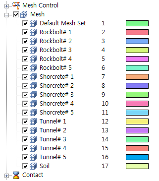
The mesh
set is created as follows.

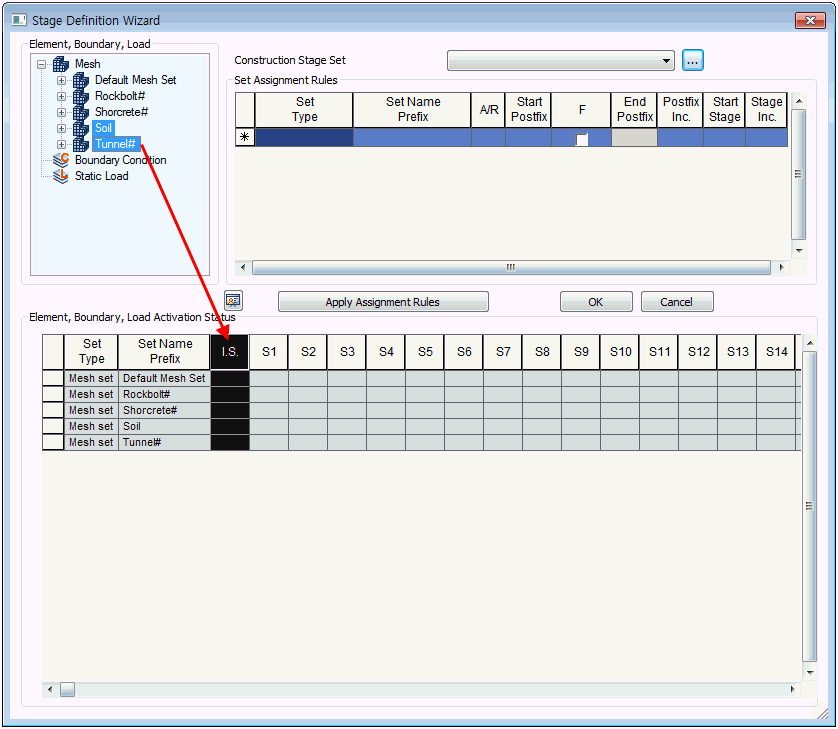
Run the
Stage definition wizard.
'Soil'
and 'Tunnel#' need to be included in the in-situ
state. Select using the Ctrl key and drag &
drop into the I.S. column of the Mesh, Boundary,
Load activation status.

Start the
tunnel excavation.
In this
example, the exaction is done stage by stage,
starting from the first stage as follows: 1st
face tunnel excavation -> 1st face rock bolt/shotcrete
installment -> 2nd tunnel excavation ->
2nd face rock bolt/shotcrete installment ->
….
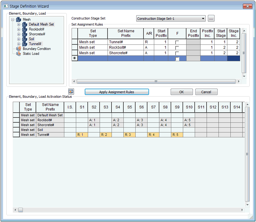
Select
R to select and delete the 'Tunnel#' of the element
type, the Start postfix as 1 and do not check
F to process until the last number. The Start
stage is 1 and the input is 2 for the Stage spacing
to allow for the installation of rock bolts and
shotcrete between excavation stages. Afterwards,
click the [Apply Assignment Rules] button to specify
the construction stage of the Mesh, Boundary,
Load activation status.
The shotcrete
and rock bolts are also specified on the construction
stage.
Input 2
for the Start stage and set as A to create both
elements in the second construction stage. Also,
input Start postfix 1, do not check F and input
Postfix spacing to use all the numbers from 1
to the final number. Finally, input 2 for the
Start stage and Stage spacing to create the first
elements at the second construction stage with
two stage spacing between element creation.
Press the
[Assign Assignment Rules] button to automatically
create the Mesh, Boundary, Load activation status
and click the [OK] button to create the construction
stage.

|


