USSR (User Supplied Subroutine)
▒ Contents
01. Function Description and Limitation 02. FORTRAN File Preparation 03. DLL File Preparation 04. Using the USSR material model in midas GTS |
01. Function Description and Limitation
The user supplied material function allows users to customize their own material nonlinear model in conjunction with existing Pre/Post processing features in midas GTS. Basically, the user supplied material subroutine is expected to update the integration point total stress and internal variables as well as compute the tangent modulus utilizing the basic data such as total strain, strain increment, etc.
Nonlinear elastic material and Nonlinear elasto-plastic material can be defined in the user supplied material function, and support elements that are Plane strain (3, 4, 6, 8 node element), Axisymmetric (3, 4, 6, 8 node element) and Solid (4, 6, 8, 10, 15, 20 node element). Stress components for each element type are defined as follows.
|


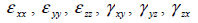
<Table 1. Stress component of element>
Requirements for midas GTS user supplied material function are listed below:
Preparing a FORTRAN File
Compiling and creating a DLL File
Using the user supplied material model in midas GTS.
02. FORTRAN File Preparation
User supplied material functions can be written using either a FORTRAN 77 or FORTRAN 90 programming language; however, since the midas GTS solver uses FORTRAN 90, users are encouraged to follow the same language. In order for the midas GTS solver to recognise the user subroutine, the name of the subroutine as well as the data types of the arguments must exactly match those given below.
!***************************************************************************
! USER SUPPLIED MATERIAL SUBROUTINE
!***************************************************************************
SUBROUTINE USRMAT_GTS(EPS0, DEPS, NS, INFM_STEP, COORD, SE, USRVAL, NUV, & USRSTA, NUS, IUSRIND, NUI, SIG, STIFF, ID, DETJ)
IMPLICIT NONE
!DEC$ ATTRIBUTES DLLEXPORT::USRMAT_GTS
INTEGER, INTENT(IN) :: NS ! NUMBER OF STRESS COMPONENTS
INTEGER, INTENT(IN) :: INFM_STEP(5) ! STEP INFORMATION FOR STAGE, INCREMENT, ITERATION, ELEMENT, INTEGRATION POINT
! INFM_STEP(1) : STAGE ID
! INFM_STEP(2) : LOAD INCREMENTAL STEP ID
! INFM_STEP(3) : ITERATION STEP ID
! INFM_STEP(4) : ELEMENT ID
! INFM_STEP(5) : INTEGRATION POINT ID
INTEGER, INTENT(IN) :: ID ! MATERIAL ID OF CURRENT ELEMENT
INTEGER, INTENT(IN) :: NUV ! NUMBER OF PARAMETERS
INTEGER, INTENT(IN) :: NUS ! NUMBER OF INTERNAL STATE VARIABLES
INTEGER, INTENT(IN) :: NUI ! NUMBER OF INTEGER INDICATOR VARIABLES
REAL*8, INTENT(IN) :: DT ! INCREMENTAL TIME
REAL*8, INTENT(IN) :: EPS0(NS) ! TOTAL STRAIN AT PREVIOUS STEP
REAL*8, INTENT(IN) :: DEPS(NS) ! INCREMENTAL STRAIN
REAL*8, INTENT(IN) :: COORD(3) ! COORDINATE OF INTEGRATION POINT
REAL*8, INTENT(IN) :: SE(NS, NS) ! ELASTIC CONSTITUTIVE MATRIX
REAL*8, INTENT(INOUT) :: SIG(NS) ! TOTAL STRESS AT PREVIOUS(IN) & CURRENT(OUT) STEP
REAL*8, INTENT(INOUT) :: STIFF(NS, NS) ! TANGENT STIFFNESS AT CURRENT STEP (OUT)
REAL*8, INTENT(INOUT) :: USRSTA(NUS) ! INTERNAL STATE VARIABLES
REAL*8, INTENT(IN) :: USRVAL(NUV) ! PARAMETERS
INTEGER, INTENT(INOUT) :: IUSRIND(NUI) ! INTEGER INDICATOR VARIABLES
User Supplied Subroutine
RETURN
END SUBROUTINE USRMAT_GTS
!***************************************************************************
The descriptions of the arguments that are used to communicate between the midas GTS solver and the user subroutine are listed below:
NS : Number of stress components.
INFM_STEP : Step Information
INFM_STEP(1) : Current stage number
INFM_STEP(2) : Current load increment step
INFM_STEP(3) : Current iteration number
INFM_STEP(4) : Current element number
INFM_STEP(5) : Current integration point number
ID : Material ID of current element.
NUV : Number of material parameters.
NUS : Number of internal state variables.
NUI : Number of integer indicator variables.
EPS0 : Total strain at previous step.
DEPS : Incremental strain.
COORD : Coordinates of integration point.
SE : Elastic constitutive matrix.
SIG : Total stress at previous step; Required to be updated in the subroutine.
STIFF : Real array of tangent stiffness that needs to be computed in the subroutine.
USRSTA : Internal state variables required to be updated in the subroutine.
USRVAL : User defined material parameters.
IUSRIND : Integer indicator valuables required to be updated in the subroutine.
DT : Incremental time.
Three simple example subroutines are included for reference: 1. linear elastic material model for 3D solid elements; 2. simple nonlinear elastic constitutive model for 2D plane strain elements; 3. an example to show how to define two different nonlinear elastic material models for 3D solid elements.
[EXAMPLE 1] Linear elastic constitutive model for 3D solid element:
!***************************************************************************
! USER SUPPLIED MATERIAL SUBROUTINE
!***************************************************************************
SUBROUTINE USRMAT_GTS(EPS0, DEPS, NS, INFM_STEP, COORD, SE, USRVAL, NUV, &
USRSTA, NUS, IUSRIND, NUI, SIG, STIFF,ID, DT)
IMPLICIT NONE
!DEC$ ATTRIBUTES DLLEXPORT::USRMAT_GTS
INTEGER, INTENT(IN) :: NS ! NUMBER OF STRESS COMPONENTS
INTEGER, INTENT(IN) :: INFM_STEP(5) ! STEP INFORMATION FOR STAGE, INCREMENT, ITERATION, ELEMENT, INTEGRATION POINT
! INFM_STEP(1) : STAGE ID
! INFM_STEP(2) : LOAD INCREMENTAL STEP ID
! INFM_STEP(3) : ITERATION STEP ID
! INFM_STEP(4) : ELEMENT ID
! INFM_STEP(5) : INTEGRATION POINT ID
INTEGER, INTENT(IN) :: ID ! MATERIAL ID OF CURRENT ELEMENT
INTEGER, INTENT(IN) :: NUV ! NUMBER OF PARAMETERS
INTEGER, INTENT(IN) :: NUS ! NUMBER OF INTERNAL STATE VARIABLES
INTEGER, INTENT(IN) :: NUI ! NUMBER OF INTEGER INDICATOR VARIABLES
REAL*8, INTENT(IN) :: DT ! INCREMENTAL TIME
REAL*8, INTENT(IN) :: EPS0(NS) ! TOTAL STRAIN AT PREVIOUS STEP
REAL*8, INTENT(IN) :: DEPS(NS) ! INCREMENTAL STRAIN
REAL*8, INTENT(IN) :: COORD(3) ! COORDINATE OF INTEGRATION POINT
REAL*8, INTENT(IN) :: SE(NS, NS) ! ELASTIC CONSTITUTIVE MATRIX
REAL*8, INTENT(INOUT) :: SIG(NS) ! TOTAL STRESS AT PREVIOUS(IN) & CURRENT(OUT) STEP
REAL*8, INTENT(INOUT) :: STIFF(NS, NS) ! TANGENT STIFFNESS AT CURRENT STEP (OUT)
REAL*8, INTENT(INOUT) :: USRSTA(NUS) ! INTERNAL STATE VARIABLES
REAL*8, INTENT(IN) :: USRVAL(NUV) ! PARAMETERS
INTEGER, INTENT(INOUT) :: IUSRIND(NUI) ! INTEGER INDICATOR VARIABLES
INTEGER :: I, J
REAL*8 :: TEMP
REAL*8, ALLOCATABLE :: DSIG(:)
IF(ALLOCATED(DSIG)) DEALLOCATE(DSIG)
ALLOCATE(DSIG(NS))
DO I = 1, NS
TEMP = 0.D0
DO J = 1, NS
TEMP = TEMP + SE(I, J) * DEPS(J)
STIFF(I, J) = SE(I, J)
ENDDO
DSIG(I) = TEMP
SIG(I) = SIG(I) + DSIG(I)
ENDDO
RETURN
END
!***************************************************************************
[EXAMPLE 2] Simple nonlinear elastic constitutive model for 2D plane strain element
!***************************************************************************
! USER SUPPLIED MATERIAL SUBROUTINE
!***************************************************************************
SUBROUTINE USRMAT_GTS(EPS0, DEPS, NS, INFM_STEP, COORD, SE, USRVAL, NUV, &
USRSTA, NUS, IUSRIND, NUI, SIG, STIFF,ID, DT)
IMPLICIT NONE
!DEC$ ATTRIBUTES DLLEXPORT::USRMAT_GTS
INTEGER, INTENT(IN) :: NS ! NUMBER OF STRESS COMPONENTS
INTEGER, INTENT(IN) :: INFM_STEP(5) ! STEP INFORMATION FOR STAGE, INCREMENT, ITERATION, ELEMENT, INTEGRATION POINT
! INFM_STEP(1) : STAGE ID
! INFM_STEP(2) : LOAD INCREMENTAL STEP ID
! INFM_STEP(3) : ITERATION STEP ID
! INFM_STEP(4) : ELEMENT ID
! INFM_STEP(5) : INTEGRATION POINT ID
INTEGER, INTENT(IN) :: ID ! MATERIAL ID OF CURRENT ELEMENT
INTEGER, INTENT(IN) :: NUV ! NUMBER OF PARAMETERS
INTEGER, INTENT(IN) :: NUS ! NUMBER OF INTERNAL STATE VARIABLES
INTEGER, INTENT(IN) :: NUI ! NUMBER OF INTEGER INDICATOR VARIABLES
REAL*8, INTENT(IN) :: DT ! INCREMENTAL TIME
REAL*8, INTENT(IN) :: EPS0(NS) ! TOTAL STRAIN AT PREVIOUS STEP
REAL*8, INTENT(IN) :: DEPS(NS) ! INCREMENTAL STRAIN
REAL*8, INTENT(IN) :: COORD(3) ! COORDINATE OF INTEGRATION POINT
REAL*8, INTENT(IN) :: SE(NS, NS) ! ELASTIC CONSTITUTIVE MATRIX
REAL*8, INTENT(INOUT) :: SIG(NS) ! TOTAL STRESS AT PREVIOUS(IN) & CURRENT(OUT) STEP
REAL*8, INTENT(INOUT) :: STIFF(NS, NS) ! TANGENT STIFFNESS AT CURRENT STEP (OUT)
REAL*8, INTENT(INOUT) :: EPSP(NS) ! TOTAL PLASTIC STRAIN AT PREVIOUS STEP
REAL*8, INTENT(INOUT) :: USRSTA(NUS) ! INTERNAL STATE VARIABLES
REAL*8, INTENT(IN) :: USRVAL(NUV) ! PARAMETERS
INTEGER, INTENT(INOUT) :: IUSRIND(NUI) ! INTEGER INDICATOR VARIABLES
INTEGER :: I, J
REAL*8 :: EMOD
REAL*8, ALLOCATABLE :: EPS(:)
IF(ALLOCATED(EPS)) DEALLOCATE(EPS)
ALLOCATE(EPS(NS))
EMOD = USRVAL(1)
EPS(1:NS) = EPS0(1:NS) + DEPS(1:NS)
!-----------------------------------------------------------
! TOTAL STRESS
!-----------------------------------------------------------
SIG(1) = EMOD * EPS(1) + 1000.D0 * EMOD * EPS(1)**2
SIG(2) = EMOD * EPS(2) + 1000.D0 * EMOD * EPS(2)**2
SIG(4) = EMOD * EPS(4) + 1000.D0 * EMOD * EPS(4)**2
SIG(3) = (EMOD * EPS(3)) / 2.D0
!-----------------------------------------------------------
! MATERIAL STIFFNESS MATRIX
!----------------------------------------------------------
STIFF(1,1) = EMOD + 2000.D0 * EMOD * EPS(1)
STIFF(2,2) = EMOD + 2000.D0 * EMOD * EPS(2)
STIFF(4,4) = EMOD + 2000.D0 * EMOD * EPS(4)
STIFF(3,3) = 0.5D0 * EMOD
RETURN
END
!***************************************************************************
[EXAMPLE 3] defines two different nonlinear elastic material models for 3D solid elements. It makes use of material ID that is passed on to the subroutine to distinguish between the two different material models and take necessary action accordingly.
!***************************************************************************
! USER SUPPLIED MATERIAL SUBROUTINE
!***************************************************************************
SUBROUTINE USRMAT_GTS(EPS0, DEPS, NS, INFM_STEP, COORD, SE, USRVAL, NUV, &
USRSTA, NUS, IUSRIND, NUI, SIG, STIFF,ID, DT) IMPLICIT NONE
!DEC$ ATTRIBUTES DLLEXPORT::USRMAT_GTS
INTEGER, INTENT(IN) :: NS ! NUMBER OF STRESS COMPONENTS
INTEGER, INTENT(IN) :: INFM_STEP(5) ! STEP INFORMATION FOR STAGE, INCREMENT, ITERATION, ELEMENT, INTEGRATION POINT
! INFM_STEP(1) : STAGE ID
! INFM_STEP(2) : LOAD INCREMENTAL STEP ID
! INFM_STEP(3) : ITERATION STEP ID
! INFM_STEP(4) : ELEMENT ID
! INFM_STEP(5) : INTEGRATION POINT ID
INTEGER, INTENT(IN) :: ID ! MATERIAL ID OF CURRENT ELEMENT
INTEGER, INTENT(IN) :: NUV ! NUMBER OF PARAMETERS
INTEGER, INTENT(IN) :: NUS ! NUMBER OF INTERNAL STATE VARIABLES
INTEGER, INTENT(IN) :: NUI ! NUMBER OF INTEGER INDICATOR VARIABLES
REAL*8, INTENT(IN) :: DT ! INCREMENTAL TIME
REAL*8, INTENT(IN) :: EPS0(NS) ! TOTAL STRAIN AT PREVIOUS STEP
REAL*8, INTENT(IN) :: DEPS(NS) ! INCREMENTAL STRAIN
REAL*8, INTENT(IN) :: COORD(3) ! COORDINATE OF INTEGRATION POINT
REAL*8, INTENT(IN) :: SE(NS, NS) ! ELASTIC CONSTITUTIVE MATRIX
REAL*8, INTENT(INOUT) :: SIG(NS) ! TOTAL STRESS AT PREVIOUS(IN) & CURRENT(OUT) STEP
REAL*8, INTENT(INOUT) :: STIFF(NS, NS) ! TANGENT STIFFNESS AT CURRENT STEP (OUT)
REAL*8, INTENT(INOUT) :: USRSTA(NUS) ! INTERNAL STATE VARIABLES
REAL*8, INTENT(IN) :: USRVAL(NUV) ! PARAMETERS
INTEGER, INTENT(INOUT) :: IUSRIND(NUI) ! INTEGER INDICATOR VARIABLES
INTEGER :: I, J
REAL*8 :: EMOD
REAL*8, ALLOCATABLE :: EPS(:)
IF(ALLOCATED(EPS)) DEALLOCATE(EPS)
ALLOCATE(EPS(NS))
IF(ID == 1)THEN
SIG(1:NS) = 0.D0
EMOD = USRVAL(1)
EPS(1:NS) = EPS0(1:NS) + DEPS(1:NS)
!-----------------------------------------------------------
! TOTAL STRESS
!-----------------------------------------------------------
SIG(1) = EMOD * EPS(1) + 1000.D0 * EMOD * EPS(1)**2
SIG(2) = EMOD * EPS(2) + 1000.D0 * EMOD * EPS(2)**2
SIG(3) = EMOD * EPS(3) + 1000.D0 * EMOD * EPS(3)**2
SIG(4) = (EMOD * EPS(4)) / 2.D0
SIG(5) = (EMOD * EPS(5)) / 2.D0
SIG(6) = (EMOD * EPS(6)) / 2.D0
!-----------------------------------------------------------
! MATERIAL STIFFNESS MATRIX
!-----------------------------------------------------------
STIFF(1,1) = EMOD + 2000.D0 * EMOD * EPS(1)
STIFF(2,2) = EMOD + 2000.D0 * EMOD * EPS(2)
STIFF(3,3) = EMOD + 2000.D0 * EMOD * EPS(3)
STIFF(4,4) = 0.5D0 * EMOD
STIFF(5,5) = 0.5D0 * EMOD
STIFF(6,6) = 0.5D0 * EMOD
ELSEIF(ID == 2) THEN
SIG(1:NS) = 0.D0
EMOD = USRVAL(1)
EPS(1:NS) = EPS0(1:NS) + DEPS(1:NS)
!-----------------------------------------------------------
! TOTAL STRESS
!-----------------------------------------------------------
SIG(1) = EMOD * EPS(1) + 2000.D0 * EMOD * EPS(1)**2
SIG(2) = EMOD * EPS(2) + 2000.D0 * EMOD * EPS(2)**2
SIG(3) = EMOD * EPS(3) + 2000.D0 * EMOD * EPS(3)**2
SIG(4) = (EMOD * EPS(4)) / 2.D0
SIG(5) = (EMOD * EPS(5)) / 2.D0
SIG(6) = (EMOD * EPS(6)) / 2.D0
!-----------------------------------------------------------
! MATERIAL STIFFNESS MATRIX
!-----------------------------------------------------------
STIFF(1,1) = EMOD + 3000.D0 * EMOD * EPS(1)
STIFF(2,2) = EMOD + 3000.D0 * EMOD * EPS(2)
STIFF(3,3) = EMOD + 3000.D0 * EMOD * EPS(3)
STIFF(4,4) = 0.5D0 * EMOD
STIFF(5,5) = 0.5D0 * EMOD
STIFF(6,6) = 0.5D0 * EMOD
ENDIF
RETURN
END
!***************************************************************************
03. DLL File Preparation
To utilise the developed FORTRAN code inside midas GTS for analysis and pre-/post-processing, the user subroutine should be compiled and linked in the form of DLL (Dynamic Link Library). It is highly recommended to use the Intel FORTRAN compiler to create DLL of the user subroutine for compatibility. Other compilers are not guaranteed to work with midas GTS.
3.1 Intel FORTRAN 11.1.067
Creating DLL file using Intel FORTRAN 11.1.067
1) Select File > New > Project (Figure 1).
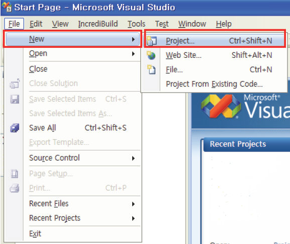
<Figure 1. Selection of project menu>
A new project window is opened. (Figure 2)
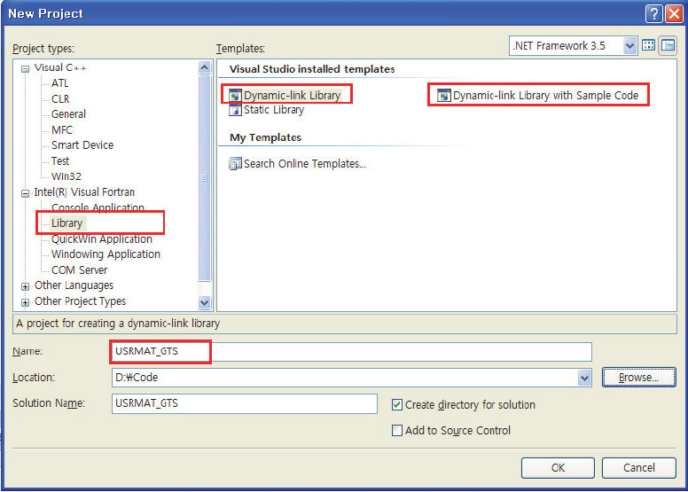
<Figure 2. Input window of new project>
2) The following example explains how to create a DLL file with a simple nonlinear elastic model [Example 2].
Figure 3 consists of defining the name of a subroutine and the list of arguments required by the user subroutine. The part where the actual calculations are executed is shown in Figure 4. Figure 5 shows the internal function defined for use within the user subroutine.
<Figure 3. USRMAT_GTS.f90 file>
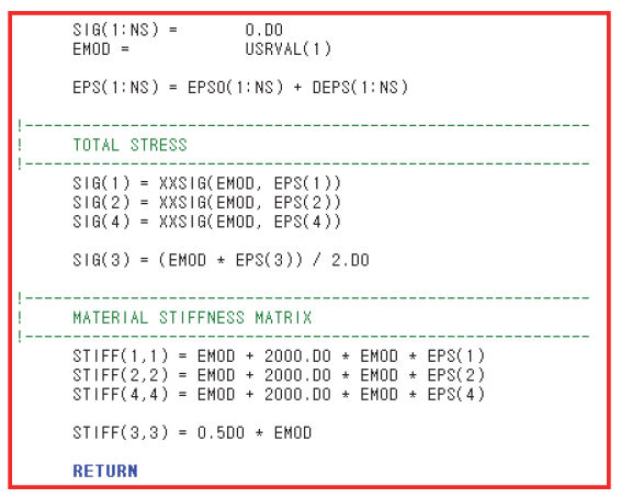
<Figure 4. Execution part input code>
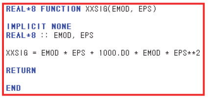
<Figure 5. Function input code>
Select ‘Release’ from the Solution Configuration at the top of Intel FORTRAN window. Click the ‘Build Solution’ function under ‘Build’ menu as shown in Figure 6 to start the build process. The message shown in Figure 7 will appear on the Output window when the compiler successfully generated the DLL file
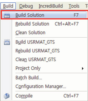
<Figure 6. Build Solution>
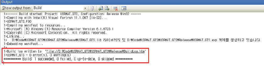
<Figure 7. Successful Build>
04. Using the user-defined material model in midas GTS
The Add/Modify Ground Material dialogue box, as shown in Figure 8, contains constitutive models in the midas GTS Solver. By selecting the Isotropic constitutive model as “User supplied material”, the “Non-Linear Parameters” subsequently are enabled: Number of Parameters (NUV), Number of Internal State Variables (NUS), and Number of Indicator Variables (NUI). This section provides descriptions about the parameters and required procedures.
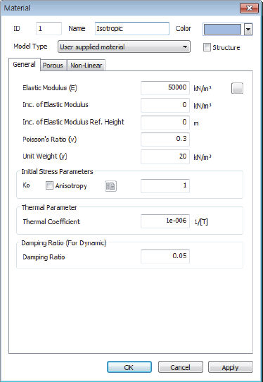
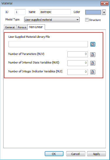
<Figure 8. Ground Material input window>
※
Modulus of Elasticity (E) and Poisson’s Ratio (![]() ) in general tab are used for
computing linear elastic constitutive matrix which is passed on
to the user subroutine. Therefore this should be entered as initial
values for nonlinear analysis. Unit Weight and Unit Weight (Saturated)
values will continue be used to compute the external weight load
by the GTS solver.
) in general tab are used for
computing linear elastic constitutive matrix which is passed on
to the user subroutine. Therefore this should be entered as initial
values for nonlinear analysis. Unit Weight and Unit Weight (Saturated)
values will continue be used to compute the external weight load
by the GTS solver.
1. User Supplied Material Library File
By
clicking on  , as shown in Figure 8, users
can select the DLL file generated from the above steps.
, as shown in Figure 8, users
can select the DLL file generated from the above steps.
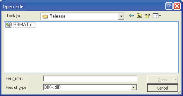
<Figure 9. DLL file open window>
2. Number of Parameters (NUV)
NUV indicates the number of
material parameters that are passed on to the user subroutine
as USRVAL. By clicking
on the adjacent icon  , as shown in Figure
8, the values of the material parameters can be viewed or changed.
Generally material coefficients defining the Constitutive
model, for instance, if the Mohr-Coulomb model is used, then the
coefficients such as Cohesion and Friction angle should be included
in the USRVAL.
, as shown in Figure
8, the values of the material parameters can be viewed or changed.
Generally material coefficients defining the Constitutive
model, for instance, if the Mohr-Coulomb model is used, then the
coefficients such as Cohesion and Friction angle should be included
in the USRVAL.
If
 is clicked, as shown in Figure 8, then
the parameters can be entered by following the procedure outlined
below:
is clicked, as shown in Figure 8, then
the parameters can be entered by following the procedure outlined
below:
Procedure:
1) Input the coefficients into the corresponding rows as shown in Figure 10.
2) Click “Enter Key” after inputting each value.
*Note: If users do not press the “Enter Key” then the value will be set to 0. Users can input up to 100 data parameters. The unit must be in N-m.
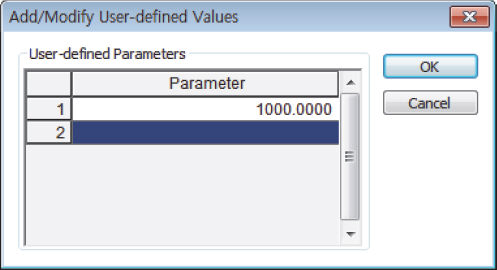
<Figure 10. User-defined value input window>
3. Number of Internal State Variables (NUS)
Internal State Variables “NUS” are usually used to store state variables such as the plastic strain components. Unlike NUV, NUS can be modified in the FORTRAN routine.
If
 selected, as shown in Figure 8, then
the initial internal state variables can be entered by following
the procedure outlined below:
selected, as shown in Figure 8, then
the initial internal state variables can be entered by following
the procedure outlined below:
Procedure:
1) Input the coefficients for each corresponding row in Figure 11.
2) Click “Enter Key” after inputting each value.
Note: If users do not press the “Enter Key” then the value will be considered as 0. Users can input up to 100 data parameters. The unit must be in N-m.
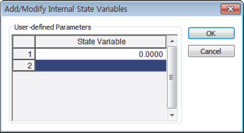
<Figure 11. Internal State Variable input window>
4. Number of Integer Indicator Variables (NUI)
Internal
Integer variable(NUI)
are used for indicator values such as the plasticity status. Unlike
the NUV, NUI can also
be modified in the FORTRAN routine. If  is selected, as shown in Figure 8, then the initial values of
the integer indicator variables can be entered by following the
procedure outlined below:
is selected, as shown in Figure 8, then the initial values of
the integer indicator variables can be entered by following the
procedure outlined below:
Procedure:
1) Input the Integer Indicator Variable for each corresponding row in Figure 12.
2) Press “Enter Key” after entering each value.
Note: If users do not press the “Enter Key” then the value will be set to 0. Users can input up to 100 data parameters.
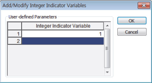
<Figure 12. User-defined Integer Indicator Variable input window>
![]()
Debugging is not possible within the midas GTS program. For complex material models, it is recommended that a separate FORTRAN driver programme be used to check the user material subroutine and to eliminate bugs. For the purpose of checking the values of variables within the midas GTS programme, the file no. 6 can be used, which is provided by GTS. Output results can be checked in the model name.out file.

|