Select
the 2D element or 3D element boundary surface to be revolve
extruded and set the rotation axis, rotation angle and
number of divisions. The element can be created by extruding
in 1 direction or 2 directions. The original element used
in extrude can be deleted/moved/copied. For move, the
used element is moved to the end of the extruded element.
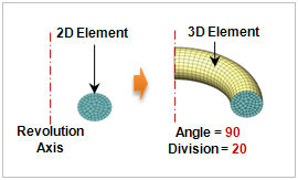 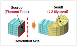
<2D element->3D revolve
extrude> <Element
Face->3D revolve extrude>
Rotation Axis
Select
the rotation axis with reference to the GCS or input the
start and end points of the direction vector using the
2 points vector function. It is useful when setting the
reference axis in an arbitrary direction.
When
using the GCS, use the [Locate] option to set the revolution
axis position using its coordinates. The revolution axis
is moved to the coordinate position and the node is rotate
extruded about the moved axis.
Revolution Information
Set
the rotation angle and division of 1D element will be
created. The division spacing can be set as either uniform
or non-uniform. Entering a positive angle rotate extrudes
in the counterclockwise direction and entering a negative
angle rotate extrudes in the clockwise direction.
[Non-uniform]
Specify
the rotation angle. The angle can be listed using a comma
(,) or as number@angle for continuously repeating angles.
For
example, entering 10@20 continuously creates 10 elements
that are rotated 20 degrees from the previous element
and entering 10,20,30 creates 3 elements, each rotated
by 10 degrees, 20 degrees and 30 degrees.
[Uniform]
Set
the rotation angle and number, or input the total rotation
angle and division spacing. |