|
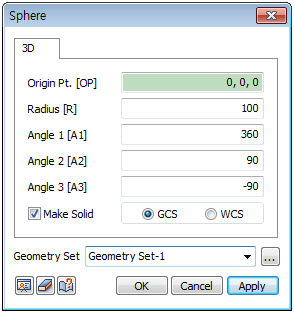
Create a sphere from the Origin point (OP) and Angles (A1, A2, A3).
Origin point (OP)
The center point coordinates of the sphere. The user can directly specify the center point of the workplane or geometry shape by selecting the points with the mouse. Because the workspace is 2-dimensional, the y- axis value is not entered.
Angle (A1, A2, A3)
The angle input to create a sphere. The values represent:
A1: Rotation angle of the sphere's vertical plane
A2: Start angle of the sphere's vertical plane (0<A2≤90)
A3: End angle of the sphere's vertical plane (-90≤A3≤0)
Make Solid
Check this option to create a solid type cylinder with a volume. Un-checking the option will create a shell type cylinder.
Enter the center coordinates with reference to the Global coordinate system. In this case, the center coordinates are input in 3D space.
Enter the center coordinates with reference to the Workplane coordinate system. In this case, the center coordinates are input in 2D space.

For GCS (Global coordinate system) and WCS (Workplane coordinate system), please refer to General information-Manage modeling toolset.
Geometry set
Register the created cylinder on the Geometry set. The user can specify the name of the Geometry set.
|