|
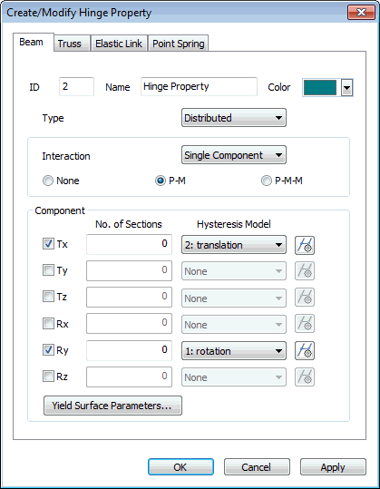
 Hinge Components (Single) Hinge Components (Single)
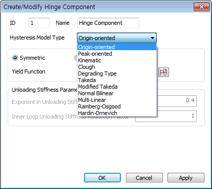
Hysteresis Model Type
- Origin-oriented : Response points at the initial loading move along a trilinear skeleton curve. Response points at unloading move toward the origin and again move along the skeleton curve after reaching the opposite skeleton curve.
- Peck-oriented : Response points at the initial loading move along a trilinear skeleton curve. Response points at unloading move toward the point of maximum displacement on the opposite side. If the first yielding has not occurred on the opposite side, the response points move toward the first yielding point on the skeleton curve.
- Kinematic : Response points at the initial loading move along a trilinear skeleton curve. The unloading stiffness is identical to the elastic stiffness. It shows the tendency of strength increase with the increase in loading. This is used to model the Bauschinger effect of metallic materials. Accordingly, it is cautioned that energy dissipation may be overestimated for concrete. Due to the characteristic of the model, only the positive (+) and negative (-) symmetry is permitted for the strength reduction ratios after yielding.
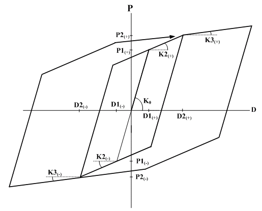
- Clough : Response points at the initial loading move along a bilinear skeleton curve. Unloading stiffness is obtained from the elastic stiffness reduced by the equation below. As the deformation progresses after yielding, unloading stiffness reduces gradually.
where,
KR : unloading stiffness
Ko : elastic stiffness
Dy : yield displacement in the zone where unloading begins
Dm : maximum displacement in the zone where unloading begins
(In the zone where yielding has not occurred, replace it with the yield displacement)
 : constant for determining unloading stiffness : constant for determining unloading stiffness
If the sign of loading changes in the process of unloading, response points move toward the point of maximum displacement in the zone of progressing direction. If yielding has not occurred in this zone, the response points move toward the yield point on the skeleton curve. If unloading becomes loading without changing the loading sign, the response points move along the unloading path. If the loading continually increases, loading continues on the skeleton curve again.
- Degrading : Response points at the initial loading move along a trilinear skeleton curve. The load-displacement coordinates at unloading move to the path of reaching the maximum deformation point on the opposite side due to the change of unloading stiffness once in the middle. If yielding has not occurred on the opposite side, the first yielding point is assumed to be the maximum deformation point.
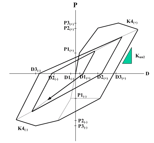
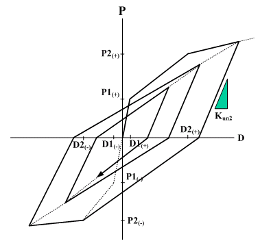
- Takeda : Response points at the initial loading move along a tetralinear skeleton curve. If the current displacement or deformation, D, does not exceed D3, the hysteresis rules are identical to the Original Taketa hysteresis. If the current displacement or deformation, D, exceeds D3, response points move along the slope K4. For unloading, response points move by the same rules as the Original Taketa hysteresis. The Takeda tetralinear hysteresis model can be applied to beam element and General Link of Spring Type of Lumped Type and Distributed Type.
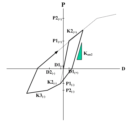
- Modified Takeda : Response points at the initial loading move along a trilinear skeleton curve. If the current displacement or deformation, D, exceeds D2 for the first time or the maximum deformation point up until now, response points move along the trilinear skeleton curve. If unloading takes place from this straight line toward the opposite direction, the points move along the slope Kun2 until the point of the restoring force becoming 0. If the restoring force goes beyond the 0 point, the points move toward the maximum deformation point on the opposite side. Even in the case where unloading takes place from the straight line directed toward the maximum deformation point from the point of the 0 restoring force, the points move along the slope Kun2 until the points reach the 0 restoring force. After the point of 0 restoring force is passed, the points move toward the maximum deformation point on the opposite side. The Modified Takeda type hysteresis model can be applied to beam element and General Link of Spring Type of Lumped Type and Distributed Type.
- Normal Bilinear : Response points at the initial loading move along a bilinear skeleton curve. The unloading stiffness is identical to the elastic stiffness. The Normal Bilinear type hysteresis model can be applied to beam element and General Link of Spring Type of Lumped Type and Distributed Type.
- Modified Ramberg-Osgood :
- Modified Hardin-Drnevich :

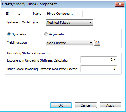
Symmetric / Asymmetric
: Select the type of Skeleton Curve.
Yield Function
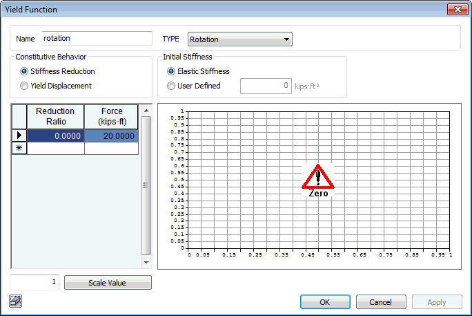
- Stiffness Reduction Ratio : Enter the stiffness reduction ratios of a sloped skeleton curve when Strength - Stiffness Reduction Ratio is selected for Input Type.
- Yield Displacement : Enter the yield displacement of a sloped skeleton curve when Strength - Yield Displacement is selected for Input Type.
- Force (Yield Strength) : Yield strength is specified. It is user defined based on material and section properties. The user specifies positive (+) values regardless of tension (t) or compression (c). The program treats compression as negative (-) internally.
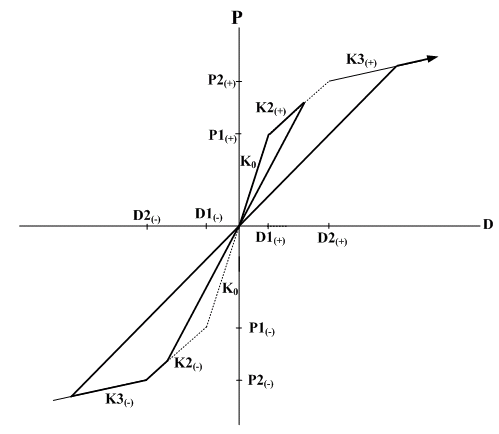
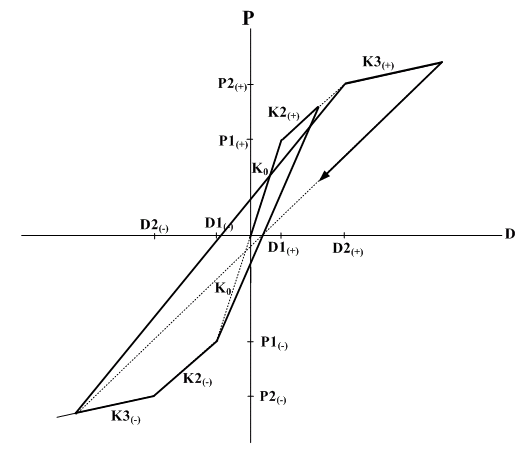
Unloading Stiffness Parameter
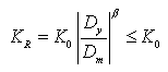
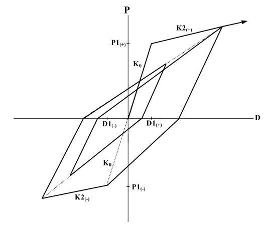
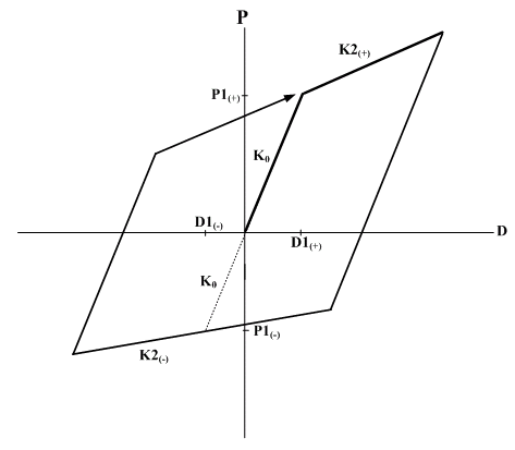
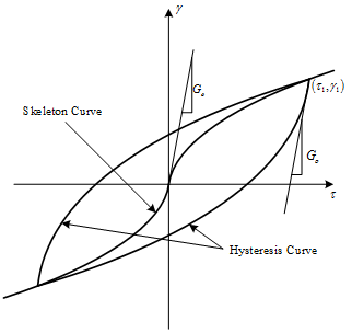
Exponent in Unloading Stiffness Calculation: This is an option used to determine the unloading stiffness of the outer loop used in the Clough and Takeda type models among hysteresis models of skeleton curves. This is used to reflect the effect of reduction in stiffness, which occurs as the deformation progresses after yielding. The unloading stiffness is determined by the elastic stiffness reduced by the yield displacement and maximum displacement in the zone where unloading begins and the exponent entered here.
Inner Loop Unloading Stiffness Reduction Factor: This is used to determine the unloading stiffness of the inner loop. The inner loop is formed when unloading occurs before reaching the target point on the skeleton curve while reloading after the loading sign changes in the process of unloading. The unloading stiffness of the inner loop is calculated by multiplying the unloading stiffness of the outer loop by the reduction ratio for the unloading stiffness of the inner loop.
Hinge Components (Multi)
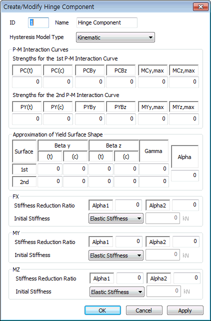
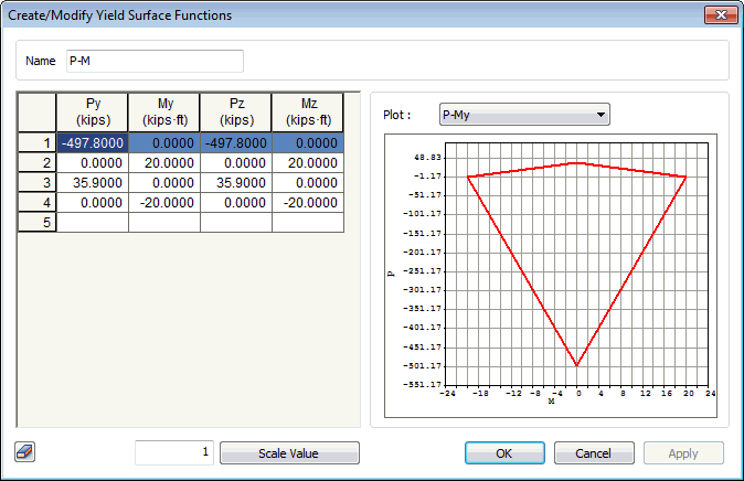
- P-M Interaction Curves : Enter the P-M interaction curve data required to calculate 3-dimensional yield surfaces. All strength values must be entered with positive sign. Sign convention for plotting P-M curve is positive for compression and negative for tension.
Strengths for the 1st P-M Interaction Curves
PC(t): First yield strength subject to pure tension force
PC(c): First yield strength subject to pure compression force
PCBy: Axial force at the time of balanced failure in the first yield interaction curve for the y-axis moment of the section
PCBz: Axial force at the time of balanced failure in the first yield interaction curve for the z-axis moment of the section
MCy,max: Maximum bending yield strength in the first yield interaction curve for the y-axis moment of the section
MCz,max: Maximum bending yield strength in the first yield interaction curve for the z-axis moment of the section
Strengths for the 2nd P-M Interaction Curves
PY(t): Second yield strength subject to pure tension force
PY(c): Second yield strength subject to pure compression force
PYBy: Axial force at the time of balanced failure in the second stage yield interaction curve for the y-axis moment of the section
PYBz: Axial force at the time of balanced failure in the second yield interaction curve for the z-axis moment of the section
MYy,max: Maximum bending yield strength in the second yield interaction curve for the y-axis moment of the section
MYz,max: Maximum bending yield strength in the second yield interaction curve for the z-axis moment of the section
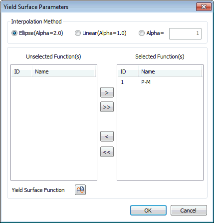
- Approximation of Yield Surface Shape : On the basis of P-M interaction curve, the parameters for 3-dimensional yield surface are either user defined or auto-calculated. If some items are auto-calculated and the remainder is to be user defined, Auto-calculation should be performed first, and then necessary items can be modified after converting to User Input. In case of Alpha, only user defined entry is possible. The value of each parameter is used in the equation of yield surface displayed in the dialog box.
Beta y, Beta z, Gamma: Being the exponential powers of P-My or P-Mz interactions, different values can be entered for the first and second yields. For Beta y and Beta z on the other hand, two separate values representing the ranges of larger and smaller axial forces relative to the axial force at the time of balanced failure can be entered.
Alpha: Exponent for My-Mz interaction for the 1st and 2nd yielding
- Stiffness Reduction Ratio : Enter the stiffness reduction ratios of a sloped skeleton curve when Strength - Stiffness Reduction Ratio is selected for Input Type.
α1: Ratio of stiffness immediately after the first yielding divided by the initial stiffness
α2: Ratio of stiffness immediately after the second yielding divided by the initial stiffness
- Initial Stiffness : The initial stiffness used in inelastic analysis is either selected or entered by the user.
Elastic Stiffness: elastic stiffness of a member is used as the initial stiffness for inelastic analysis.
User Defined: the user directly enters the initial stiffness if the Input Type is Strength - Stiffness Reduction Ratio.
|