1D
element
1D
element is an element that is made up of 2(primary) or
3(secondary) nodes and has the geometric property of length.
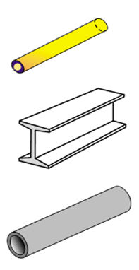
Because 3D shapes are expressed as 1D elements, the section
(size, shape) needs to be defined and this is modeled
as a 2D element for calculations.
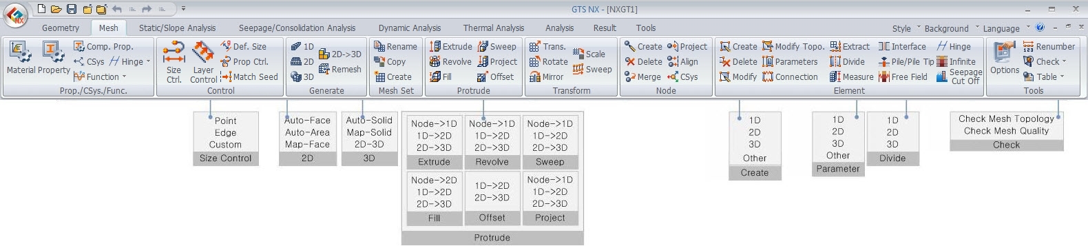
GTS
NX provides various shapes, as shown in the figure below.
The position can also be set when defining the sectional
properties.
<Actual model> <Finite
element model>
QUAD-4 6400개
<Solid
square> |
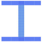
QUAD-4 3400개
<H section> |
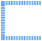
QUAD-4 1700개
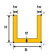
<Channel> |
<Automatic section modeling
>
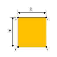
<Solid
Rectangle>
|
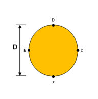
<Solid
Round>
|
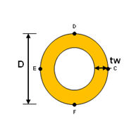
<Pipe>
|
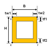
<Box>
|
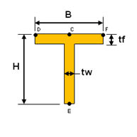
<T-section>
|
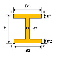
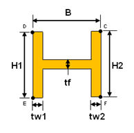
<H-section>
|
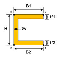
<Channel>
|
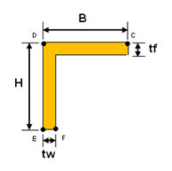
<Angle>
|
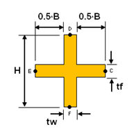
<Cross>
|
<I-section>
|
<Channel
1>
|
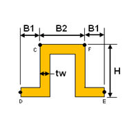
<Hat>
|
<U
Section> |
<Z Section>
|
|
<Section shape and size specification>
1D element SRC Section
/SRC_section_DB/SRC.PNG)
<SRC Section DB>
SRC(Steel
Reinforced Concrete) can be defined under 1D element(truss,
beam, embedded truss, embedded beam).
It
has added SRC-Box, SRC-Pipe, Sect-HBeam, Circle-HBeam
in the section of 1D element. User can define the section
selecting the database of steel and concrete, elastic
modulus of steel will use for calculation.
/SRC_section_DB/SRC2.PNG)
Steel
Data: Input the parameter of steel section or selecting
the section from database.
Concrete
Data: Input the outer dimensions of section for steel
concrete
Material:
Select the material for SRC or input the parameters. The
parameters will be inputted automatically selecting the
database from [Select Material from DB…].
Es/Ec:
Elastic ratio between steel and concrete
Ds/Dc:
Deadweight ratio between steel and concrete
Ps:
Poisson’s ratio of steel
Pc:
Poisson’s ratio of concrete
Conv.
Stiffness Factor: Stiffness reduction factor of concrete
(default=1.0) for SRC section

2D element
2D
elements are Triangles or Quadrilaterals with the geometric
property of area. Because 3D shapes are expressed as 2D
elements, the thickness needs to be defined. The thickness
can be set the same or tapered.
<Actual model> <Finite
element model>
3D element
3D
elements are Tetrahedron or Hexahedrons, Bricks with the
geometric property of volume.
<Actual model> <Finite
element model>
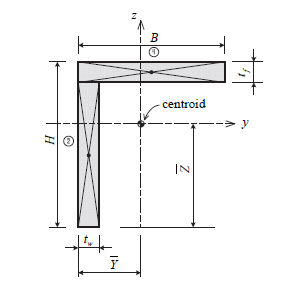
Cross sectional area (A)
The
cross sectional area is used to calculate the axial stiffness
when a tensile or axial force acts on the member or the
stress on a member. The calculations for the H section
are as follows.
There
are 2 methods to calculate the cross sectional area in
the GTS NX. The first method uses the provided database
to input the dimensions of a section and automatically
calculate the area. For the second method, the user calculates
the area directly and inputs the value. The first method
is convenient, but because it does not consider the decrease
in area due to bolts in the connection or rivet holes,
the area entered using the second method may provide more
accurate results.
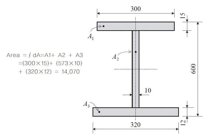
<Example of cross sectional
area calculation>
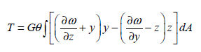
Torsional stiffness (Ixx)
The
torsional stiffness resists the torsional moment and is
expressed as follows.

Here, : Torsional stiffness, : Torsional stiffness,
 : Torsional
moment or torque, : Torsional
moment or torque,
 : Torsional angle
(angle of twist), : Torsional angle
(angle of twist),
 : Shear modulus : Shear modulus
The
torsional stiffness is the stiffness that resists the
torsional moment and is different from the polar moment
of inertia that decides the shear stress due to torsion.
(However, the 2 are the same when considering a
circular cross-section or a thick cylindrical section)
The
torsional stiffness can be calculated from Saint-Venant's
principle as shown below.
 is the warping function is the warping function  that can be calculated using the Finite element method
as shown below.
that can be calculated using the Finite element method
as shown below.
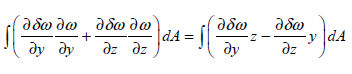
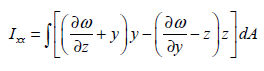
Because
 , the torsional stiffness comp1nt
is expressed as the following equation. , the torsional stiffness comp1nt
is expressed as the following equation.
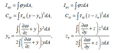
Effective shear area (Asy,
Asz )
The
effective shear area is needed to calculate the shear
stiffness that resists the shear force acting on the y
axis or z axis of the element coordinate system. If the
effective shear area is not entered, the shear strain
in that direction is ignored.

Here,
 : Effective
shear factor that resists shear force in the y axis of
the element coordinate system : Effective
shear factor that resists shear force in the y axis of
the element coordinate system
 : Effective
shear factor that resists shear force in the z axis of
the element coordinate system : Effective
shear factor that resists shear force in the z axis of
the element coordinate system
 : Effective shear
area that resists shear force in the y axis of the element
coordinate system : Effective shear
area that resists shear force in the y axis of the element
coordinate system
 : Effective shear
area that resists shear force in the z axis of the element
coordinate system : Effective shear
area that resists shear force in the z axis of the element
coordinate system
When
the interior section material properties are calculated
or entered from the database, the shear stiffness comp1nt
is automatically considered and the effective shear factor
is calculated using the warping function  from the shear
force caused by bending moment and the warping function from the shear
force caused by bending moment and the warping function
 from the Saint-Venant principle. from the Saint-Venant principle.
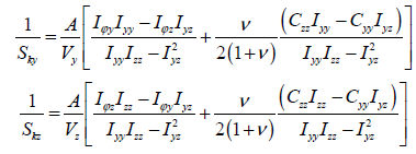
Here,
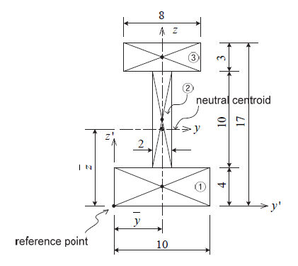
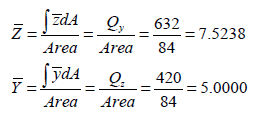
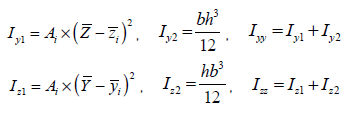
Area moment of inertia (Iyy, Izz)
The
area moment of inertia is used to calculate the flexural
stiffness that resists the bending moment and is calculated
from the centroid axis of the section using the following
equation.

Section
element |
b |
h |

|

|

|

|

|
① |
10 |
4 |
40 |
2 |
80 |
5 |
200 |
② |
2 |
10 |
20 |
9 |
180 |
5 |
100 |
③ |
8 |
3 |
24 |
15.5 |
372 |
5 |
120 |
total |
- |
- |
84 |
- |
632 |
- |
420 |
<Table. First area moment of
inertia and calculation of centroid >
:
area
: distance from
the reference point to the centroid of the section element
in the z′-axis direction
: distance from the reference
point to the centroid of the section element in the y′-axis
direction
:
first moment of area relative to the reference point
in the y′-axis direction
: first
moment of area relative to the reference point in the
z′-axis direction
Section
element |

|

|

|

|

|

|

|

|

|
① |
40 |
5.5328 |
1224.5 |
53.3 |
1277.8 |
0 |
0 |
333.3 |
333.3 |
② |
20 |
1.4672 |
43.1 |
166.7 |
209.8 |
0 |
0 |
6.7 |
6.7 |
③ |
24 |
7.9762 |
1526.9 |
18.0 |
1544.9 |
0 |
0 |
128.0 |
128.0 |
total |
|
2794.5 |
238.0 |
3032.5 |
|
0 |
468.0 |
468.0 |
|
<Table. Second area moment of
inertia example>
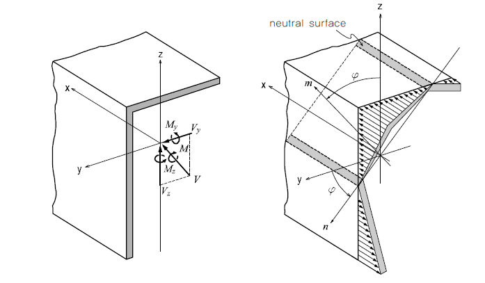
Area product moment of inertia
(Iyz)
The
area product moment of inertia is used to calculate the
stress comp1nt of an asymmetrical section and the definition
is as follows.
H,
pipe, box, channel, tee type sections have at least 1
axis of symmetry out of the y,z axis on the element coordinate
system and hence Iyz=0. For angle type sections, it does
not have any angle of symmetry (Iyz≠ 0) and so, the stress
comp1nt needs to be calculated.
The
calculations for the area product moment of inertia of
an angle type section are shown in the figure below.
 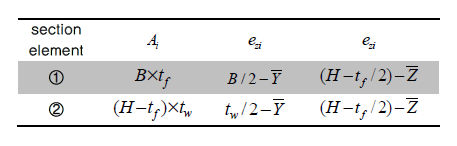
<Area product moment of inertia
calculations for an angle section>
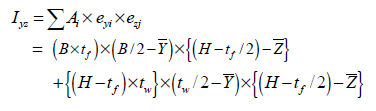
< Flexural stress distribution
diagram for asymmetrical section>
The
neutral axis is the axis that passes the points where
the flexural stress due to the bending moment is ‘0(zero)’
within the member. The neutral axis is perpendicular to
the -axis and the -axis.
Because
the flexural stress due to bending moment is ‘0’ on the
neutral axis, the neutral axis direction can be found
by the following equation.
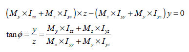
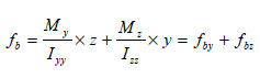
The
general equation used to calculate the flexural stress
due to bending moment is as follows.
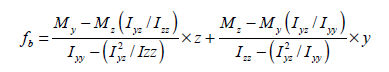
If
this is a H type section,  and,
and,
Here,
 : Second area moment
of inertia about the axis of the element coordinate
system, : Second area moment
of inertia about the axis of the element coordinate
system,
 : Second area moment of inertia
about the axis of the element coordinate system, : Second area moment of inertia
about the axis of the element coordinate system,
 : Area product moment of inertia, : Area product moment of inertia,
 : Elemental axis
distance from neutral axis to where the flexural stress
is calculated, : Elemental axis
distance from neutral axis to where the flexural stress
is calculated,
 : Elemental axis
distance from neutral axis to where the flexural stress
is calculated, : Elemental axis
distance from neutral axis to where the flexural stress
is calculated,
 : Bending moment about the axis
of the element coordinate system, : Bending moment about the axis
of the element coordinate system,
 : Bending moment about the axis
of the element coordinate system : Bending moment about the axis
of the element coordinate system
The
shear stress due to shear force acting in the axis
and axis direction of the element coordinate system
can be calculated using the following equation.
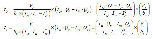
Here,
 : Shear force acting
in the axis direction of the element coordinate system, : Shear force acting
in the axis direction of the element coordinate system,
 : Shear force acting in the
axis direction of the element coordinate system, : Shear force acting in the
axis direction of the element coordinate system,
 : First area moment of
inertia about the axis of the element coordinate system, : First area moment of
inertia about the axis of the element coordinate system,
 : First area moment of inertia
about the axis of the element coordinate system, : First area moment of inertia
about the axis of the element coordinate system,
 : Section thickness at the point
where shear stress is calculated in the normal direction
to the elemental axis, : Section thickness at the point
where shear stress is calculated in the normal direction
to the elemental axis,
 : Section thickness at the point
where shear stress is calculated in the normal direction
to the elemental axis : Section thickness at the point
where shear stress is calculated in the normal direction
to the elemental axis
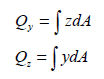
First moment of area (Qy,
Qz)
The
first moment of area is used to calculate the shear stress
at an arbitrary point on the section and the shear stress
can be calculated using the following equation.
For
a section that is symmetrical about the y, z or both axis,
the shear strength on an arbitrary point can be calculated
using the following equation.
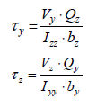
Here, : Shear force acting in the
axis direction of the element coordinate system, : Shear force acting in the
axis direction of the element coordinate system,
 : Shear force acting in the
axis direction of the element coordinate system, : Shear force acting in the
axis direction of the element coordinate system,
 : Second area moment of inertia
about the axis of the element coordinate system, : Second area moment of inertia
about the axis of the element coordinate system,
 : Second area moment of inertia
about the axis of the element coordinate system, : Second area moment of inertia
about the axis of the element coordinate system,
 : Section thickness at the point
where shear stress is calculated in the normal direction
to the elemental axis, : Section thickness at the point
where shear stress is calculated in the normal direction
to the elemental axis,
 : Section thickness at
the point where shear stress is calculated in the normal
direction to the elemental axis : Section thickness at
the point where shear stress is calculated in the normal
direction to the elemental axis
Element thickness
On
the GTS NX, the thickness needs to be defined to specify
the 2D plane stress element, 2D geogrid element, plate
element, plane strain element, axial symmetry element,
linear interface element etc. Here, the plane strain element,
axial symmetry element and linear interface element have
an interior unit weight of 1.
The
plane stress element, 2D geogrid element and plate element
use the thickness value entered by the user. The plate
element has a rotor float and because nonlinear analysis
is possible, a separate integration is performed in the
thickness direction.
Spacing
This
functionality is in the 1D element property which is activated
only in 2D project setting. Since this option is used
to consider the 1D element force per each element when
the user introduce the 1D element more or less than one
along the axis of horizontal direction (thickness direction)
in 2D model.
If
the user uncheck the spacing option, on the GTS NX, the
spacing will be regarded as Plane Strain Thickness in
the analysis setting, meaning that the unit thickness
based on the selected unit system.
On
the GTS NX, spacing is used to calculate the stiffness
of the element and output the member force per each element.
where,
n = spacing, L = length , A = area, K* = stiffness considering
spacing.
where,
f* = member force
Refer
to the following example,
|

 ,
,  )
)