General Link Properties
| ||||||||||||||||||||||||||
|
| ||||||||||||||||||||||||||
|
| ||||||||||||||||||||||||||
|
Add, modify or delete the properties of general link elements.
General Link elements are used for modeling damping devices, base isolators, compression or tension-only elements, plastic hinges, soil springs, etc. General Link elements can be assigned linear and nonlinear properties using spring properties.
The procedure for boundary nonlinear dynamic analysis is shown below.
| ||||||||||||||||||||||||||
|
| ||||||||||||||||||||||||||
|
| ||||||||||||||||||||||||||
|
| ||||||||||||||||||||||||||
|
From the Main Menu select Model > Boundaries > General Link Properties.
Select Geometry > Boundaries > General Link Properties in the Menu tab of the Tree Menu. | ||||||||||||||||||||||||||
|
| ||||||||||||||||||||||||||
|
| ||||||||||||||||||||||||||
|
Define General Link Properties dialog box
|
 To enter or add new properties
of general link elements, click the
To enter or add new properties
of general link elements, click the  button.
 button and change appropriate
data entries.
button and change appropriate
data entries. button and change appropriate
data entries.
button and change appropriate
data entries.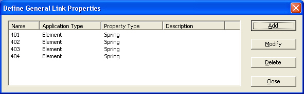
 Name
Name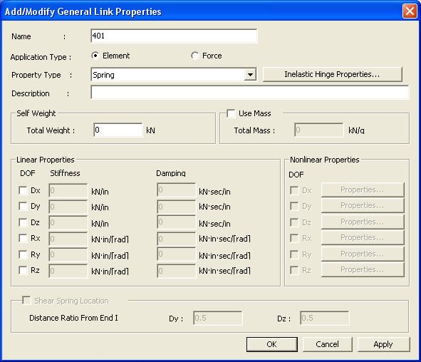

|
|
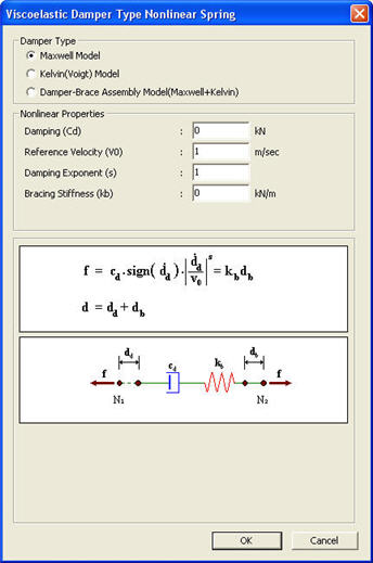
Damping (Cd): Damping coefficient of viscoelastic damper
Reference Velocity (V0): Value to make velocity term dimensionless
Note In general, 1.0 will be entered, but it depends on the change in the length units . Damping Exponent (s): Exponent defining the nonlinear viscosity damping property of the viscoelastic damper (Viscosity damping force acts in the opposite direction to the deformation rate and is proportional to the absolute value of the deformation rate to the power of s).
Note Viscosity damper can be modeled as either a linear viscosity damper ( s=1), which is proportional to the deformation rate, or a nonlinear viscosity damper (0.0<s<1.0), which is proportional to the deformation rate to the power of s. In general, Damping Exponent is 0.35~1.00.
Bracing Stiffness (kb): Stiffness of connecting member (specify the value) |
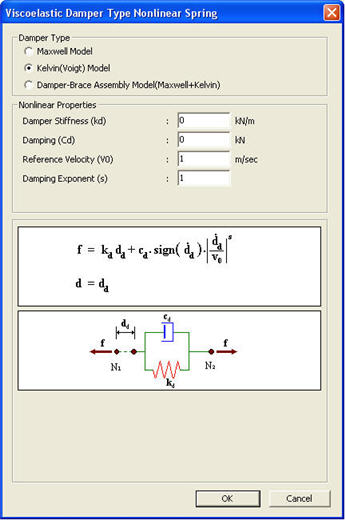
Damper Type = Kelvin (Voigt) Model
Kelvin Model consists of a linear spring and a viscosity damper connected in parallel, as shown in the figure below, and is used for Solid Viscoelastic Device analysis.
Force-displacement relationship of Kelvin Model is given as below. Since the right side is all known terms, the force acting in viscoelastic damper can be obtained from the equation.
|
|
Damper Stiffness (kd): Stiffness of viscoelastic damper
Damping (Cd): Damping coefficient of viscoelastic damper
Reference Velocity (V0): Value to make velocity term dimensionless
Note In general, 1.0 will be entered, but it depends on the change in the length units.
Damping Exponent (s): Exponent defining the nonlinear viscosity damping property of the viscoelastic damper (Viscosity damping force acts in the opposite direction to the deformation rate and is proportional to the absolute value of the deformation rate to the power of s).
Note Viscosity damper can be modeled as either a linear viscosity damper (s=1.0), which is proportional to the deformation rate,or a nonlinear viscosity damper(0.0<s<1.0)which is proportional to the deformation rate to the power of s. In general, Damping Exponent is 0.35~1.00. |
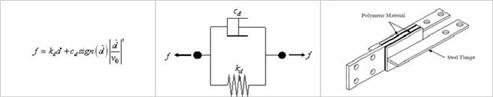
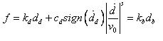
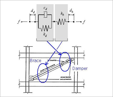
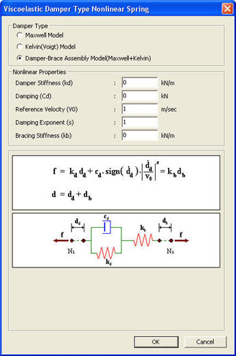
Damper Type = Damper Brace Assembly Model
Damper Brace Assembly Model is a Kelvin Model connected by a spring, as shown in the figure below, and is used for analyzing the bracing as a vibration control device.
Force-displacement relationship of Damper Brace Assembly Model is given as below. Since the right side is all known terms, the force acting in viscoelastic damper can be obtained from the equation.
|
|
Damper Stiffness (kd): Stiffness of viscoelastic damper
Damping (Cd): Damping coefficient of viscoelastic damper
Reference Velocity (V0): Value to make velocity term dimensionless
Note In general, 1.0 will be entered, but it depends on the change in the length units.
Damping Exponent (s): Exponent defining the nonlinear viscosity damping property of the viscoelastic damper (Viscosity damping force acts in the opposite direction to the deformation rate and is proportional to the absolute value of the deformation rate to the power of s).
Note Viscosity damper can be modeled as either a linear viscosity damper (s=1.0), which is proportional to the deformation rate, or a nonlinear viscosity damper (0.0<s<1.0), which is proportional to the deformation rate to the power of s. In general, Damping Exponent is 0.35~1.00.
Bracing Stiffness (kb): Stiffness of connecting member (specify the value) |
-
Gap consists of 6 springs. The deformations of the node N2 relative to the node N1 for all 6 degrees of freedom in the element coordinate system can be represented. If the absolute values of the negative relative deformations become greater than the initial gaps in the springs, the stiffnesses of the corresponding springs will be activated. A linear viscosity damping coefficient can be additionally entered in parallel with each Gap spring.
Stiffness (k): Stiffness of gap spring
Open (o): Initial gap within the Gap spring
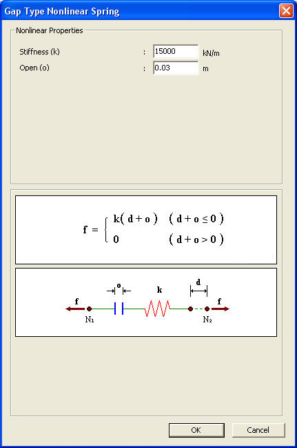
Gap Type Nonlinear Spring dialog box
-
Hook consists of 6 springs. The deformations of the node N2 relative to the node N1 for all 6 degrees of freedom in the element coordinate system can be represented. If the absolute values of the positive relative deformations become greater than the initial slippage distances in the springs, the stiffnesses of the corresponding springs will be activated. A linear viscosity damping coefficient can be additionally entered in parallel with each Hook spring.
Stiffness (k): Stiffness of hook spring
Open (o): Initial slippage distance within the hook spring
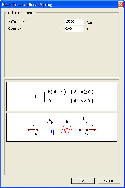
Hook Type Nonlinear Spring dialog box
-
Hysteretic system consists of 6 independent springs having the properties of Uniaxial Plasticity. In addition, a linear viscosity damping coefficient can be entered in parallel with each Hysteretic System spring.
Stiffness (k): Initial elastic spring stiffness before yielding
Yield Strength (Fy): Yield strength of spring
Post Yield Stiffness Ratio (r): Ratio of post-yield stiffness to elastic stiffness prior to yielding
Yielding Exponent (s): Parameter determining the shape of Force-Deformation curve near the yield strength transition region (Larger values lead close to the Bi-linear shape.)
Hysteretic Loop Parameter (α): Parameter determining the shape of hysteretic curve
Hysteretic Loop Parameter (β): Parameter determining the shape of hysteretic curve
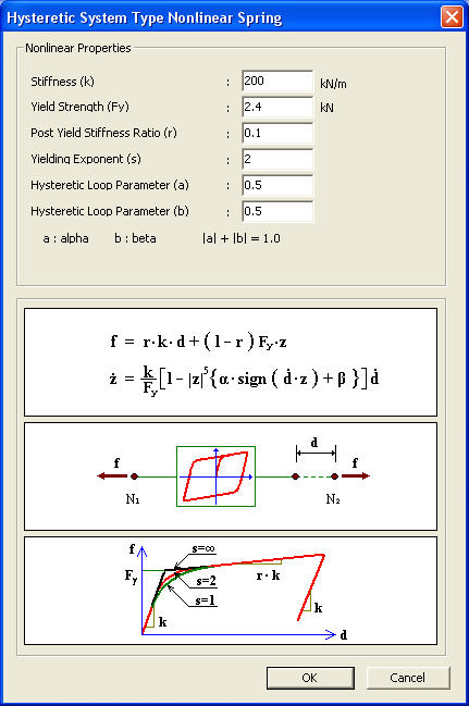
Hysteretic System Type Nonlinear Spring dialog box
-
Lead Rubber Bearing Isolator retains the properties of coupled Biaxial Plasticity for the 2 shear deformations and the properties of independent linear elastic springs for the remaining 4 deformations. In addition, a linear viscosity damping coefficient can be entered in parallel with the spring of each degree of freedom.
The parameters defining the shear deformation springs are as follows:
Stiffness (k): Initial elastic spring stiffness before yielding
Yield Strength (Fy): Yield strength of spring
Post Yield Stiffness Ratio (r): Ratio of post-yield stiffness to elastic stiffness prior to yielding
Hysteretic Loop Parameter (α): Parameter determining the shape of hysteretic curve
Hysteretic Loop Parameter (β): Parameter determining the shape of hysteretic curve
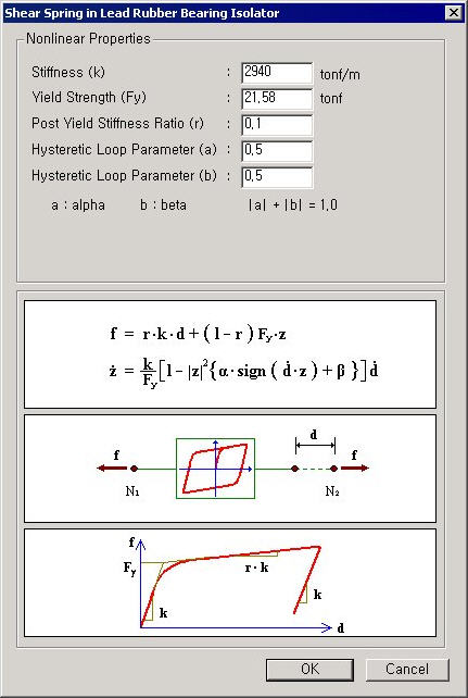
Shear Spring in Lead Rubber Bearing Isolator dialog box
The parameters defining the axial deformation and 3 rotational deformation springs are as follows:
Stiffness (k): Stiffness of spring
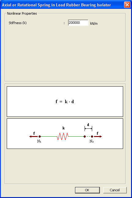
Axial or Rotational Spring in Lead Rubber Bearing Isolator dialog box
Friction Pendulum System Isolator
Friction Pendulum System Isolator retains the properties of coupled Biaxial Plasticity for the 2 shear deformations, the nonlinear property of the Gap behavior for the axial deformation and the properties of independent linear elastic springs for the remaining 3 rotational deformations. The Force-Deformation relationship of the axial spring of the friction pendulum system type isolator is identical to that of Gap with the initial gap of 0. In addition, a linear viscosity damping coefficient can be entered in parallel with the spring of each degree of freedom.
The parameters defining the axial deformation spring are as follows:
Stiffness (k): Stiffness of spring
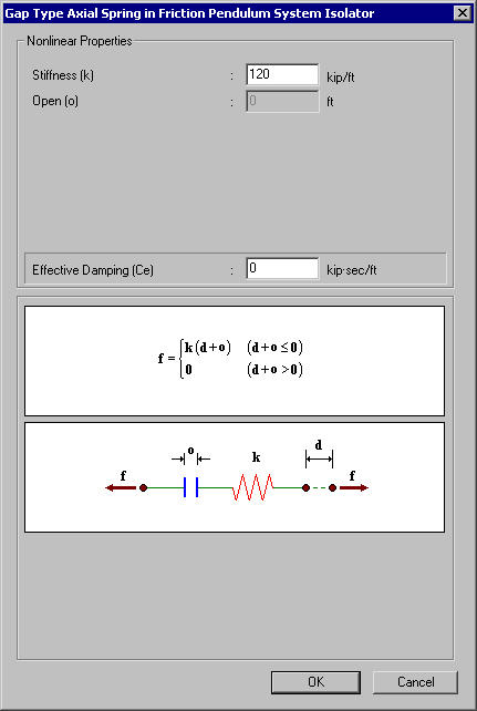
Gap Type Axial Spring in Friction Pendulum System Isolator dialog box
The parameters defining the shear deformation springs are as follows:
Stiffness (k): Initial shear stiffness prior to sliding
Friction Coefficient, Slow (μs): Friction coefficient for slow deformation velocity
Friction Coefficient, Fast (μs): Friction coefficient for fast deformation velocity
Rate Parameter (r): Rate of the change of friction coefficient with respect to the deformation velocity
Radius of Sliding Surface (R): Radius of the sliding surface curvature
Hysteretic Loop Parameter (α): Parameter determining the shape of hysteretic curve of shear spring
Hysteretic Loop Parameter (β): Parameter determining the shape of hysteretic curve of shear spring
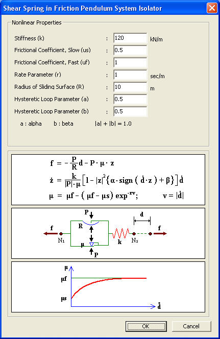
Shear Spring in Friction Pendulum System Isolator dialog box
The parameters defining the 3 rotational deformation springs are as follows:
Stiffness (k): Stiffness of spring
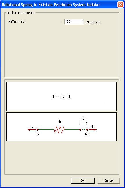
Rotational Spring in Friction Pendulum System Isolator dialog box