6
degrees-of-freedom are considered by default for each node when constraints
are not defined by the user.
Use the function to exclude unnecessary
degrees-of-freedom to ensure the efficiency of the analysis. Quite often,
only 2-D behaviors or behaviors with a particular degree-of-freedom constrained
are of interest.
3
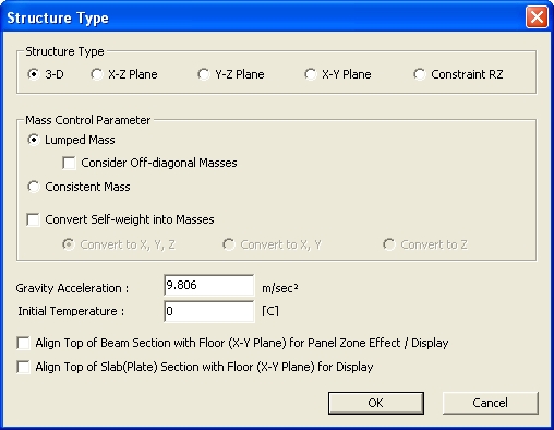
- D 6 degrees-of-freedom per node applicable for a general 3-D structural analysis.
X
- Z Plane 2-D structural analysis on the GCS X-Z plane. (The Y-direction displacements
and the rotations about the X and Z-axes are automatically constrained.)
Y
- Z Plane 2-D structural analysis on the GCS Y-Z plane. (The X-direction displacements
and the rotations about the Y and Z-axes are automatically constrained.)
X
- Y Plane 2-D structural analysis on the GCS X-Y plane. (The Z-direction displacements
and the rotations about the X and Y-axes are automatically constrained.)
Constraint RZ Special 3-D analysis constraining the rotation(torsion) about the vertical
GCS axis (GCS Z-axis). The analysis may be applied to a preliminary design
of a structure, such as to analyze a lateral shear force distribution
for each story.
Revision of V.7.6.1
Mass Control Parameter
Define mass type as
Lumped Mass or Consistent Mass.
The user can consider
whether to convert the model self-weight into lumped/consistent masses
for dynamic analysis using the Convert Self-weight into Masses option.
Lumped
Mass
Convert into lumped
masses.
The total mass of an
element is directly distributed to the nodal points of an element. In
general, only the diagonal terms of the lumped mass matrix are considered
for mass calculations. As such, this matrix is considered as a vector.
Consider Off-diagonal Masses
When this option is
checked on, all terms including off-diagonal terms in the lumped mass
matrix are considered for mass calculations. The accuracy of results increases
with a full lumped mass matrix, but the analysis time may increase.
When a section offset
is considered, a node will be generated at the offset location and the
loads, boundary conditions, masses, etc. to be applied to the node will
be entered to the node at the offset location. However, structural characteristics
related to elements (e.g., element stiffness, loads to be applied to the
elements, masses converted from self-weight of elements, etc.) have to
be entered at the centroid of a section. If this option is checked, masses
converted from self-weight of elements are entered at the centroid of
a section. Nodal mass and nodal load, which is entered at the node and
has no relation to elements, will be entered at the offset node.
Consistent Mass
Convert into distributed masses.
Consistent Mass is calculated with the
shape function used to derive the stiffness matrix. Off-diagonal mass
terms are considered and, unlike the lumped mass, the inertia coupling
effect is considered. Therefore, results using the consistent mass is
more accurate than the lumped mass, however it takes more time for numerical
computation.
Consistent masses can
be applied only when the "Lanczos" option is selected in the
Eigenvalue Analysis Control.
Convert Self-weight into
Masses
Convert
to X, Y, Z: Convert the self-weight into lumped masses in the GCS
X, Y, Z-directions
Convert
to X, Y: Convert the self-weight into lumped masses in the GCS
X, Y-directions
Convert
to Z: Convert the self-weight into lumped masses in the GCS Z-direction
The masses of the elements included in the model can
be automatically converted into lumped masses in MIDAS/Gen for dynamic
analysis or computation of statically equivalent seismic loads. When
dynamic analysis is performed with "no not convert" option checked,
mass effect cannot be reflected in the analysis.
If 'Convert
to X, Y, Z' is selected, the mass,
which is the weight divided by the acceleration of gravity, is automatically
considered in the GCS X, Y, Z-directions. The weight itself is automatically
obtained by multiplying the volumetric weight (density) entered in Model
> Properties >Material by the volume of the element.
If
'Convert to X, Y'
is selected, the calculated mass is automatically considered in the GCS
X, Y-directions.
If
'Convert to Z'
is selected, the calculated mass is automatically considered in the GCS
Z-direction.
In most cases of building structures, lateral
behaviors are more important than vertical behaviors. Thus, the vertical
components of masses are commonly neglected. The condition of 'Convert
to X, Y' saves analysis time and lessens the burden of computer memory
capacities.
Where
structures are analyzed considering only the vertical component of the
seismic data or dynamic analyses are required to evaluate machine vibrations
on floor slabs and other vertical vibrations, 'Convert to Z' may be more
appropriate. The notion is identically applied when masses are generated
by "Nodal Masses" or
"Load to Masses".
For line elements (truss element, tension
element, compression element, beam element), each element mass is divided
by two and distributed to both ends as lumped masses.
For plane elements (plane
stress element, plate element) and solid elements, each element mass is
divided by the number of nodal corners and lumped to each node as lumped
masses.
Self weight cannot be converted into mass
in Load to Mass. It must be converted in Structure Type.
Gravity acceleration
Enter the acceleration of gravity considering
the unit system in use.
Align Top of Beam Section with Floor (X-Y Plane)
for Panel Zone Effect/Display
Align the tops of line elements in the GCS
X-Y plane such that their top elevations line up at the floor level (nodal
positions of columns) when reflecting rigid offsets or displaying the
elements in the Model Window. (Refer to "Rigid Offset Distance")
Note
In order to see Panel Zone Effect applied, "Auto Calculate Panel Zone
Offset Distances" should be defined first in Model > Boundaries
>Panel
Zone Effect.
Align Top of Slab (Plate) Section with Floor (X-Y
Plane) for Display
Align the tops of plate elements in the GCS
X-Y plane such that their top elevations line up at the floor level (nodal
positions of columns) when displaying the elements in the Model Window.
Note
When the alignment options
are not selected, the centerlines of the line and plate elements are shown
to be connected to the column nodes.
 Structure Type
 Revision of V.7.6.1