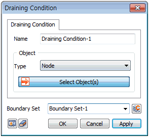
Select
the point to assign Drainage conditions.
The target can be selected
from [Node], [Edge], [Face], [Free Face Node].
For [Node], the node is
directly selected to define the node on which
the Drainage conditions will be assigned. Selecting
[Edge] or [Face] applies Drainage conditions for
all nodes in the geometry shape.
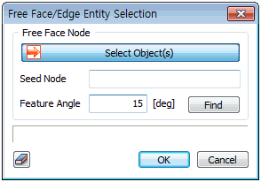
For [Free Face Node], select
a free face node and all points that make contact
with the node-containing element at an angle smaller
than the specified angle are selected. Press the
 button to select the reference node, target
element and feature angle.
button to select the reference node, target
element and feature angle.
The excess pore pressure
in an area with assigned drainage conditions is
maintained as 0 and this implies that water can
escape due to loading applied to the ground. The
Drainage condition is mainly used when the permeability
coefficient is large, or if the loading change
is small.
Boundary
Set
Register the set constraint
conditions on the desired boundary set. The user
can specify the name of the boundary set. |