Directly
input the head value of a specific point. The target can
be selected from [Node], [Edge], [Face], [Free Face Node].
For
[Node], the node is directly selected to define the head
condition. Selecting [Edge] or [Face] defines the head
condition at all nodes in the selected line/face.
For
[Free Face Node], select a free face node and all points
that make contact with the node-containing element at
an angle smaller than the specified angle. Press
 to open the Free face/line
entity selection window to select the target. to open the Free face/line
entity selection window to select the target.
There
are two input methods:
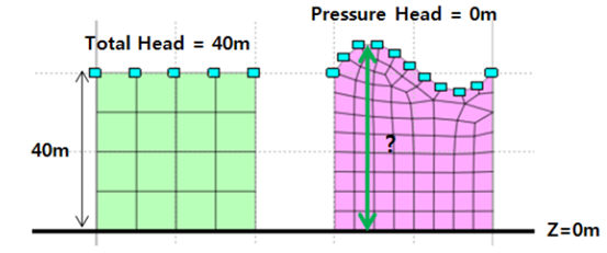
1.
[Total] : Input the head value calculated from the origin,
regardless of the model position.
2.
[Pressure] : Set the groundwater level condition by entering
'0' for nodes that are on the groundwater surface.
Transient
analysis, in which the water level changes with time,
can be defined as a function.
When
using a function, the input value and function value are
multiplied and reflected in the analysis.
The
defined function is registered under Function > Seepage
Boundary Function, and can be edited as a table using
right mouse click > Edit.
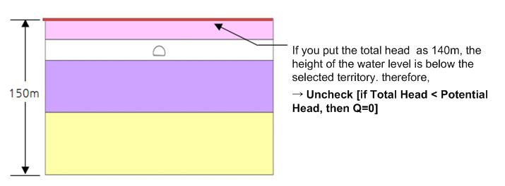
If Total Head < Pressure Head,
then Q = 0
A
head-flow rate conversion boundary condition for water
level variation analysis.
As
the water level changes with time, such as for rapid drawdown,
suction can occur and the seepage flow can be reversed.
If the water level falls suddenly for embankments or dams,
the descending water level speed is generally faster than
the seepage speed within the body. To simulate these real
conditions, the head boundary conditions need to change
automatically according to the water level. In other words,
when the node boundary at the bottom of the water level
is exposed to the top, the total nodal head is not the
total head of the descended water level; it is the total
head value before the descent, which is maintained for
a certain period, after which it falls gradually with
time.
This
option can be applied where the water level changes periodically
and can be applied simultaneously with a time variant
function. However, if this option is checked when the
input (total head) height of the water level is above
the selected node position, the boundary condition is
automatically eliminated and so, the option must be unchecked
for this case.
Boundary condition set
Register
the set constraint conditions on the desired boundary
condition set. The user can specify the name of the boundary
condition set.
|