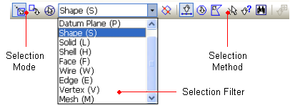
Selection Method
![]()
GTS offers various selection methods and handling capabilities in the Work Window to effectively generate a model.
When the user brings the mouse pointer above a desired entity, it will be highlighted with a sky-blue edge. Therefore, the user can preliminarily check whether the selection is being made correctly or not. Once the entity is selected, the boundary color will be changed to pink.
GTS provides the following options in the Selection Toolbar.
|
Selection Mode |
|
Select (0) |
Add to selection. |
|
|
Unselect (0) |
Remove from selection. | |
|
|
Unselect all the selected entities. | ||
|
Selection Method |
|
Include Intersected (Ctrl) |
Select all the entities that are contained inside the selecting area as well as the entities intersecting the defined boundaries. |
|
|
Pick / Window (1) |
Select the entities by clicking the mouse once each time. Or select the entities in rectangular bounding area defined by dragging the mouse cursor. | |
|
|
Circle (2) |
Select all the entities in circular bounding area defined by dragging the mouse cursor. | |
|
|
Polygon (3) |
Select the entities by successively clicking the corners of the polygon containing the relevant entities with the mouse cursor. | |
|
|
Polyline (4) |
Select the entities by crossing a series of lines that intersect the desired entities with the mouse cursor. | |
|
|
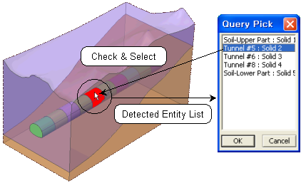
Query Pick (5) |
Select the entity from the list of the entities which are detected at the mouse click in the Work Window. | |
|
|
Displayed (Ctrl+A) |
Select all the entities which are currently shown in the Work Window. | |
|
|
Select the node(s) or the element(s) by entering its Node ID or Element ID. |


<Selection Toolbar Configuration>
![]() The number in the parenthesis indicates the
shortcut key for each selection method. This only works when the focus
is on the Work Window.
The number in the parenthesis indicates the
shortcut key for each selection method. This only works when the focus
is on the Work Window.
![]() In GTS, the user can specify the snap sensitivity.
It controls the selection range when the mouse pointer detects a particular
entity. The snap sensitivity can be set in Tools > Preference >
Environment > View > Selection & Snap Sensitivity. It is easier
to select if the sensitivity is too high, but in case of complex modeling,
it may be difficult to perform delicate selection work. Especially, when
selecting a node, it is important not to increase the sensitivity value
too high.
In GTS, the user can specify the snap sensitivity.
It controls the selection range when the mouse pointer detects a particular
entity. The snap sensitivity can be set in Tools > Preference >
Environment > View > Selection & Snap Sensitivity. It is easier
to select if the sensitivity is too high, but in case of complex modeling,
it may be difficult to perform delicate selection work. Especially, when
selecting a node, it is important not to increase the sensitivity value
too high.
This command is used to change into Select mode when the user selects the entities. The user can change to the Unselect mode by typing ??on the keyboard or by pressing the middle button of the mouse.
This command is used to change into Unselect mode when the user only unselects the entities. The user can change to Select mode by typing ??on the keyboard or by pressing the middle button of the mouse.
This command is used to Unselect all the selected entities. Double-clicking the mouse scroll button also executes this function. The user must pay attention during the Unselect All command while using the mouse because, depending on the double-clicking speed, the user may mistakenly switch between the Select and Unselect modes.
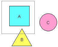
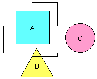
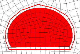
When operated along with the Window, Circle or Polygon command, the Include Intersected command selects all the entities that are contained inside the selection area as well as the entities intersecting the boundaries of the area. The user can toggle the Include Intersected mode on and off by pressing the <Ctrl> key while dragging the selection area. During the Include Intersected mode, the selection boundary is drawn in dotted lines.
|
Window Selection(Incl. Intersected: Off) |
Window Selection(Incl. Intersected: On) |
Using the Pick / Window Select command, the desired entities can be selected by clicking the mouse once each time. The Window Select feature can be activated by dragging the mouse from one corner to the other.
Pick Select
Select the desired entities by clicking the mouse once each time. To unselect the selected entities, click them once again in the Select Mode.
Window Select
Click the diagonal corners of a window area containing the entities with the mouse cursor, and select or unselect the desired entities completely contained within the rectangular window. Press the <Esc> key to cancel while defining the window area.
Enter "1" key to change to the Pick / Window Selection method during the modeling process.
Select the desired entities that are contained within the circular bounding area. The circular area is defined by clicking the center point and dragging out to the desired radius. Press the <Esc> key to cancel while defining the circular area. Enter ?span style="font-weight: bold;">2?key to change to the Circle Selection method during the modeling process.
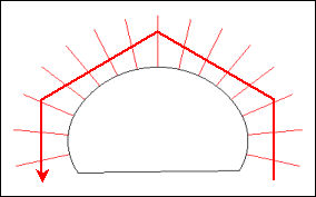
This command is used to select or unselect the desired entities by successively clicking the corners of the polygon containing the relevant entities with the mouse cursor. While clicking the final corner, double-click the mouse to end the command. Press the <Esc> key to cancel while defining the polygon. Enter ?span style="font-weight: bold;">3? key to change to the Polygon selection method during the modeling process.
This command is used to select or unselect
the desired entities by crossing a series of lines that intersect the
entities with the mouse cursor in the Model Window. While clicking the
final point of the last line, double-click the mouse to end the command.
Press the <Esc> key to cancel
while defining the polyline. Enter ?span style="font-weight: bold;">4?
key to change to the Polyline selection method during the modeling process.
|
<Circle Selection> |
<Polygon Selection> |
<Polyline Selection> |
This command is used to select or unselect the desired entity from the list of all the entities which are detected at the location of the mouse click. Going down the list, each entity on the list will be highlighted. The desired entity is selected by clicking the OK button. Enter ?span style="font-weight: bold;">5?key to change to the Query Pick Selection method during the modeling process.
This command is used to select or unselect all the entities shown in the Work Window. Simply click the Displayed icon in the Selection Toolbar.
![]() When the Work
Window is set to Zoom All, the Displayed selection will work identically
to the Select All command.
When the Work
Window is set to Zoom All, the Displayed selection will work identically
to the Select All command.
|
<Query PickSelection> |
<Display Selection> |

In the node and element selection mode, the user enters the Node or Element ID directly to select the desired entity. The user can distinguish between the Node and Element Selection Mode by the Selection Filter. If the Selection Filter shows only Node or Element, the program is in the Node and Element Selection Mode. This mode is only active for the node and element manipulation functions.
When the ID selection method is on, the ID Selection dialog box appears on the Work Window. The detailed selection procedure is as follows.
Enter the ID of either Node or Element in the Dialog Box to make the selection.
If the nodes and elements are selected by different selection methods, the IDs of the selected entities will appear in the dialog box. The user can modify the list of the selected entities.
The ID Selection dialog box consists of the following buttons.
Add
Add the nodes or elements of the newly entered ID to the selection..
Replace
Unselect the existing selection and select the nodes or elements of the newly entered ID.
Clear
Clear the list in the ID selection dialog box. Although the user can clear the Selection Dialog Box, the previously selected entities still remain selected.
Close
Close the ID selection dialog box.
![]() The ID selection is convenient for selecting
a specific element when multiple elements are located at the same point.
The ID selection is convenient for selecting
a specific element when multiple elements are located at the same point.
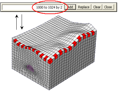
<ID Selection>
It is very difficult to select the proper entity among the many duplicated items with the mouse. In order to prevent such a problem, GTS provides the following functions:
When the selection method is on the Pick selection, the highlighted entities selected by the mouse can be alternated by pressing the Top/Down arrows of the keyboard.
![]() This is only available in the Command
Mode.
This is only available in the Command
Mode.

<Changing Selection by pressing Top/Down Arrows in the Command Mode>
The Query Pick selection can help the user to properly select the desired entity.
![]() The user can carefully check the selection from the list of the entities
which are detected at the mouse position.
The user can carefully check the selection from the list of the entities
which are detected at the mouse position.
When any function related to the selection does not operate properly, check the following items for troubleshooting:
Check whether the selection mode is the Select Mode or the Unselect Mode.
Make sure that the entity type is correctly specified in the Selection Filter.
Try again at another mouse position.
Change the selection sensitivity (allowable tolerance).
The selection sensitivity can be modified in Tools > Preferences in the Main Menu.
![]() Most cases will be resolved by 1~3, whereas
4 should be used only in special situations. If the selection sensitivity
is set too high, too many objects will be detected.
Also, the selection sensitivity can affect the snap tolerance as well.
Therefore, the user should be careful when changing the selection sensitivity.
Most cases will be resolved by 1~3, whereas
4 should be used only in special situations. If the selection sensitivity
is set too high, too many objects will be detected.
Also, the selection sensitivity can affect the snap tolerance as well.
Therefore, the user should be careful when changing the selection sensitivity.
![]() The geometric characteristics and topology
can also be implemented in the modeling process in GTS
(refer to the section on Selection
Application)
The geometric characteristics and topology
can also be implemented in the modeling process in GTS
(refer to the section on Selection
Application)