Selection Filter
![]()
![]() In order to
properly understand the Selection Filter, it is important to have a full
understanding of geometry topology in GTS. Please read Basic
Concept>Geometry Topology before
proceeding to the Selection Filter.
In order to
properly understand the Selection Filter, it is important to have a full
understanding of geometry topology in GTS. Please read Basic
Concept>Geometry Topology before
proceeding to the Selection Filter.
![]() To learn about various selection methods in GTS, please refer to Selection
Method.
To learn about various selection methods in GTS, please refer to Selection
Method.
The Selection Filter enables the user to select an object on the basis of specified entities.
Depending on the working mode and the active command, the Selection Filter performs differently, and the user will have to select the entity type within the specially customized Selection Filter.
The working mode in terms of the Selection Filter is basically distinguished by whether a command is invoked or not.
The Neutral Mode is activated when the user has not yet invoked a command, and the Selection Filter has been set to default. In the Neutral Mode, the user can only select Datum, Shapes and Mesh Sets.
![]() The Sub-Shape of a geometric entity and the
individual nodes and elements cannot be selected. It is recommended to
set the Selection Filter to Shape in the Neutral Mode.
The Sub-Shape of a geometric entity and the
individual nodes and elements cannot be selected. It is recommended to
set the Selection Filter to Shape in the Neutral Mode.
The Command Mode is activated when the user invokes a specific command and the Selection Filter has been formed with the functions relevant to that command. The user can select any desired type including the Sub-Shape, individual node and element, depending on the command type.
![]() The Selection
Filter performs differently as per the relevant command. Make sure to
check the Selection Filter before proceeding.
The Selection
Filter performs differently as per the relevant command. Make sure to
check the Selection Filter before proceeding.
|
|
|

|
Selection Filter |
Working Mode |
Selected Entities |
|
Shape |
Neutral Mode |
2 (F-1, E-1) |
|
Command Mode |
2 (F-1, E-1) | |
|
Edge |
Neutral Mode |
1 (E-1) |
|
Command Mode |
5 (E-1, E-a, E-b, E-c, E-d) |
<The difference in the Selection between the Neutral Mode
and the Command Mode>
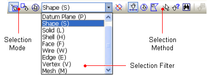
<Selection Toolbar Configuration>
The general components of the Selection Filter are shown in the following table:
|
Datum Axis (A) |
Select Datum Axis. |
|
Datum Plane (P) |
Select Datum Plane. |
|
Geometry (1) |
|
|
Shape (S) |
Select Shape. |
|
Solid (L) |
Select Solid. |
|
Shell (H) |
Select Shell. |
|
Face (F) |
Select Face. |
|
Wire (W) |
Select Wire. |
|
Edge (E) |
Select Edge. |
|
Point (V) |
Select Point |
|
Mesh |
|
|
Mesh Set (M) |
Select Mesh Set. |
|
Node (N) (2) |
Select Node. |
|
Element (E) (2) |
Select Element. |
|
Node/Element (3) |
Select Node and Element at the same time. |
|
Element-Face (4) |
Select 3D element face. |
|
Element-Edge (4) |
Select 2D element edge. |
|
(1) The Sub-Shape of geometric entities will not be selected in the Neutral Mode. (2) Only applicable in the Node and Element modifying functions. (3) Only applicable in the Incl/Excl function in the Mesh Set Menu. (4) Only applicable in the Load and Boundary Condition functions. |
|
![]() In the table, the letters in the parenthesis
indicate the shortcut keys of the Selection Filter components. The
shortcut keys only work when the focus is on the Work Window.
In the table, the letters in the parenthesis
indicate the shortcut keys of the Selection Filter components. The
shortcut keys only work when the focus is on the Work Window.
![]() In the descriptions about selection buttons
in the Online Manual, the items listed in the Selection Filter are written
in blue letters in parenthesis.
In the descriptions about selection buttons
in the Online Manual, the items listed in the Selection Filter are written
in blue letters in parenthesis.
Ex: Select Direction
Select the translation direction (Datum Axis, Datum Plane, Face or Edge): It indicates that the user can select the directions using the listed item (Datum Axis, Datum Plane, Face or Edge) in the Selection Filter.
The specified type in the Selection Filter
will be displayed at the Cursor Tip on the screen.
![]() The user can decide whether or not to display the Cursor Tip in the Display Option (View > Display Option).
The user can decide whether or not to display the Cursor Tip in the Display Option (View > Display Option).
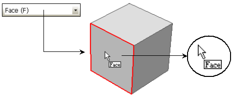
<Mouse Tool Tip Display reflecting Selection Filter>