Protrude Mesh: Fill Mesh
![]()
Function
Extrude Mesh creates elements by extruding a node to a 2D element, a 1D element to a 2D element, a Edge to a 2D element, and a 2D element to a 3D element.
Call
Mesh > Protrude Mesh >Fill
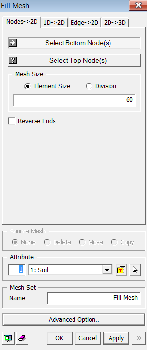
<Fill Mesh : Node->2D Dialog Box>
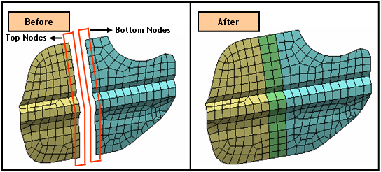
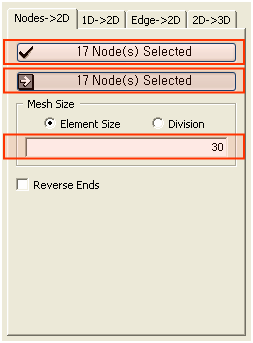
<Node -> 2D> : See its example
Select Bottom Node(s)
Select the bottom part of nodes (Mesh, Node). Numbers will be displayed on the selected nodes.
Select Top Node(s)
Select the top part of nodes (Mesh, Node). Numbers will be displayed on the selected nodes.
Note: The number of Top and Bottom Nodes must be identical, and 2D elements will be created between corresponding node numbers.
Mesh Size
Element Size
Specify
the element size.
Division
Specify the number of divisions of 3D mesh.
Reverse Ends
This option reverses the sequential order so that the last number of Top Nodes will match with the first number of Bottom Node.
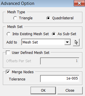
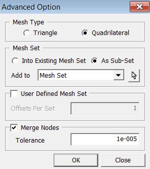
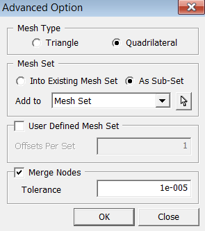
Mesh Type
Specify an element type of extruded meshes.
Triangle
Generate
Triangular 2D meshes.
Quadrilateral
Generate Quadrilateral 2D meshes.
User Defined Mesh Set
User
can specify the number of offsets per set. If one number has been entered,
it will uniformly register generated mesh by the number of offsets. If
more than one number has been entered, it will non-uniformly divide the
Mesh Set by the given numbers. The sum of the numbers should not be greater
than the total number of offsets.
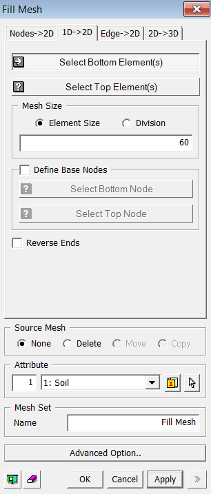
<Fill Mesh : 1D->2D Dialog Box>
<1D -> 2D>
Select Bottom Element(s)
Select
the bottom part of 1D elements (Mesh, Element).
Select Top Element(s)
Select the top part of 1D elements (Mesh, Element). The number of Top and Bottom Elements must be identical.
Note: The number of Top and Bottom Nodes must be identical, and 2D elements will be created between corresponding node numbers.
Element Size
Specify
the element size.
Division
Specify the number of divisions of 3D mesh.
Define Base Nodes
Select
Base Nodes for each Top and Bottom Elements. 2D elements will be created
by the corresponding base nodes.
Reverse Ends
This option reverses the order of Base Nodes.
Source Mesh
Specify what will be conducted to Source Meshes after it has been extruded.
None
Leave
the Source Meshes as it is.
Delete
Delete
the Source Meshes.
Move
Move
the Source Mesh to the end of extrusion.
Copy
Leave the Source Meshes as it is and copy it to the end of extrusion.
Specify an element type of extruded meshes.
Triangle
Generate
Triangular 2D meshes.
Quadrilateral
Generate Quadrilateral 2D meshes.
User Defined Mesh Set
User
can specify the number of offsets per set. If one number has been entered,
it will uniformly register generated mesh by the number of offsets. If
more than one number has been entered, it will non-uniformly divide the
Mesh Set by the given numbers. The sum of the numbers should not be greater
than the total number of offsets.
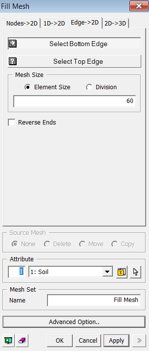
<Fill Mesh : Edge->2D Dialog Box>
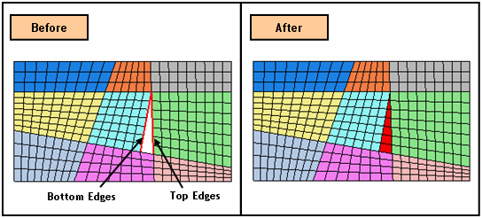
<Edge -> 2D> : See its example
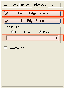
Select Bottom Edge(s)
Select
the bottom part of Edges (Edge).
If selected edge is not seeded already, the specified mesh size will be
applied in the Edges.
Select Top Edge(s)
Select
the top part of Edges (Edge).
Note: 2D elements are generated by corresponding the start point of Top and Bottom Edge.
Element Size
Specify
the element size.
Division
Specify the number of divisions of 3D mesh.
Reverse Ends
This options reverses the order of one of the Edges.
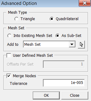
Specify an element type of extruded meshes.
Triangle
Generate
Triangular 2D meshes.
Quadrilateral
Generate Quadrilateral 2D meshes.
User Defined Mesh Set
User
can specify the number of offsets per set. If one number has been entered,
it will uniformly register generated mesh by the number of offsets. If
more than one number has been entered, it will non-uniformly divide the
Mesh Set by the given numbers. The sum of the numbers should not be greater
than the total number of offsets.
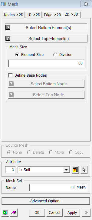
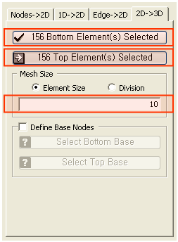
<Fill Mesh : 2D->3D Dialog Box>
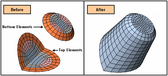
<2D -> 3D> : See its example
Select Bottom Element(s)
Select
the bottom part of 2D elements (Mesh, Element).
Select Top Element(s)
Select
the top part of 2D elements (Mesh, Element).
The number of Top and Bottom Elements must be identical.
Mesh Size
Element Size
Specify
the element size.
Division
Specify the number of divisions of 3D mesh.
Define Base Nodes
Select
Base Nodes for each Top and Bottom Elements. 2D elements will be created
by the corresponding base nodes.
Reverse Ends
This option reverses the order of Base Nodes.
Specify what will be conducted to Source Meshes after it has been extruded.
None
Leave
the Source Meshes as it is.
Delete
Delete
the Source Meshes.
Move
Move
the Source Mesh to the end of extrusion.
Copy
Leave the Source Meshes as it is and copy it to the end of extrusion.
User Defined Mesh Set
User
can specify the number of offsets per set. If one number has been entered,
it will uniformly register generated mesh by the number of offsets. If
more than one number has been entered, it will non-uniformly divide the
Mesh Set by the given numbers. The sum of the numbers should not be greater
than the total number of offsets.