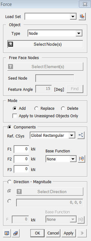
Load: Force
![]()
Function
Enter concentrated nodal Forces, or modify or delete previously entered concentrated loads.
Call
Model > Load > Force
<Force>
Load Set
Select
a Load Set in which the specified load is included
Click ![]() to the right to
prompt the Define Load Set dialog box to add, modify or delete the Load
Set. If the user types the name of the Load Set directly in the entry
box, GTS will automatically create the relevant Load Set.
to the right to
prompt the Define Load Set dialog box to add, modify or delete the Load
Set. If the user types the name of the Load Set directly in the entry
box, GTS will automatically create the relevant Load Set.
Object
Type
Select
a method of selecting a part where the loads will be assigned.
Curve
Select Curves on which the loads will be applied.
Surface
Select Surfaces on which the loads will be applied.
Node
Select the nodes directly.
Free Face Node
Select
nodes of free faces of the selected element. All nodes within the defined
angle (Feature Angle) from a seed node will be assigned.
Free Face Node
It
becomes active when the Free Face Node selection method is designated.
Seed Node
Select a Seed Node which becomes the reference for determining the free face.
Feature Angle
When
the free face selection from the Seed Node is expanded, it only selects
element nodes within the specified Feature Angle.
Click
 to select the free face nodes, and they will appear on the screen.
Mode
Add
Add new loads to the selected nodes
Replace
Replace previously defined loads on selected nodes
Delete
Delete previously defined loads on selected nodes
Apply to Unassigned Objects Only
When
adding new loads, this option applies loads only to the unassigned nodes.
Component
Enter
concentrated nodal loads with respect to the reference coordinate system.
Ref. CSys
Select
the coordinate system which becomes the reference of the load components.
Click ![]() button to the right
to prompt the Create/Modify
Coordinate System dialog box to add, modify or delete the reference
coordinate system.
button to the right
to prompt the Create/Modify
Coordinate System dialog box to add, modify or delete the reference
coordinate system.
F1
X-direction (R-direction in the cylindrical coordinate system) component of the force in the reference coordinate system.
F2
Y-direction (q-direction in the cylindrical coordinate system) component of the force in the reference coordinate system.
F3
Z-direction component of the force in the reference coordinate system.
Base Function
If
the force is defined using a function, select the relevant function. Click
![]() button to prompt the Create/Modify Function dialog
box.
button to prompt the Create/Modify Function dialog
box.
Direction-magnitude
Direction-magnitude defines a force by selecting a direction and specifying its magnitude.
Two options are available for defining the force direction. Check on the first option to select a direction from the Datum or Geometric Shape. The second option defines the direction vector.
F
Enter the magnitude of force.
Base Function
f the
force is defined using a function, select the relevant function. Click
![]() button to prompt the
Create/Modify Function dialog box.
button to prompt the
Create/Modify Function dialog box.