Coordinate System
![]()
Function
Define a user coordinate system using an Euler or 3 Point method.
Call
Model > Coordinate System
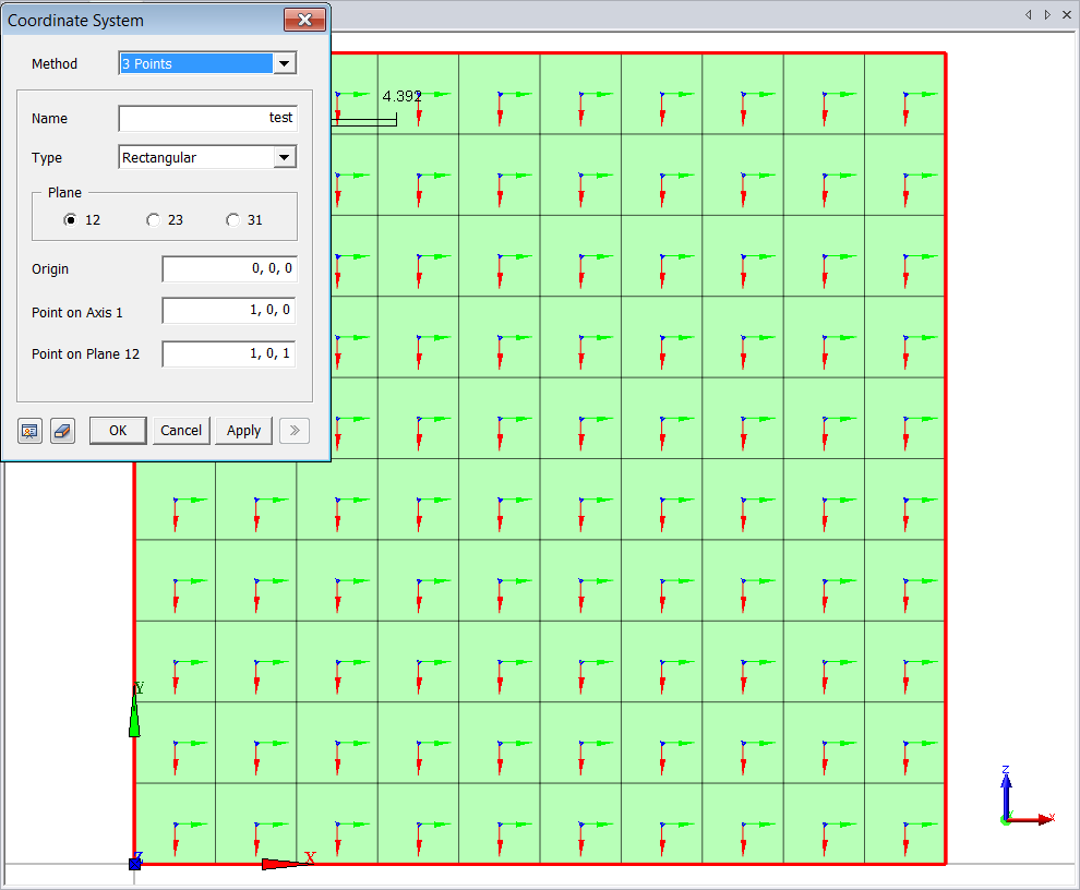
<Create/Modify CSys>
Method
Select
the defining method of coordinate system.
<3 Points>
Specify
the coordinates of 3 points to define new coordinate system. The plane
defined by 3 points becomes one of the 3 planes of the coordinate system.
Name
Enter
the name of the new coordinate system.
Type
Specify
the type of coordinate system.
Rectangular
Create
a rectangular coordinate.
Cylindrical
Create
a cylindrical coordinate.
Plane
Select
the plane which is defined by 3 points.
Origin
Define
the origin of the coordinate system. The coordinates may be specified
using Snap.
Point on Axis 1 (ex. Plane 12 is chosen)
Defines
the X-Axis in the rectangular coordinate system and R-Axis in the cylindrical
coordinate system. The coordinate may be specified using Snap features.
Point on Plane 12 (ex. Plane 12 is chosen)
Define
the third point which is located on the '12' plane (XY Plane in the rectangular
coordinate system and RT Plane in the cylindrical coordinate system).
The coordinate may be specified using Snap.
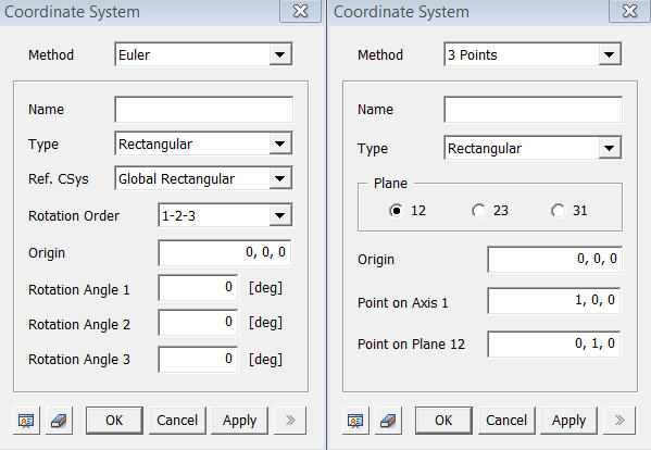
<Euler>
Define new coordinate system using Euler's angle.
Name
Enter
the name of the new coordinate system.
Type
Specify
the type of coordinate system.
Rectangular
Create
a rectangular coordinate.
Cylindrical
Create
a cylindrical coordinate.
Ref. CSys
Select
the reference coordinate system.
Rotation Order
Specify
the order of each axis for the rotation.
Origin
Define
the origin of the coordinate system. The coordinate may be specified using
Snap.
Rotation Angle 1, Rotation Angle 2, Rotation Angle 3
Specify the rotation angle for 1, 2, and 3 axis (X, Y, and Z-Axis of the rectangular coordinate system, and R, T, and Z-Axis of the cylindrical coordinate system).
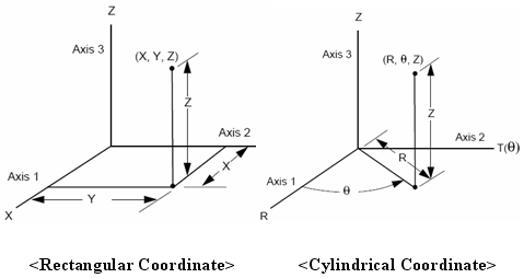
<Definition of Coordinate Systems>