Load: Dynamic Surface Loads
![]()
Function
Apply time forcing functions to specific Surfaces.
Call
Model > Load > Time History Analysis Data > Dynamic Surface Load
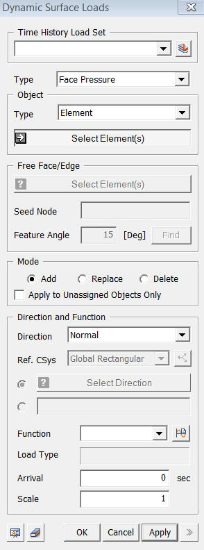
<Dynamic Surface Loads>
Load Set
Select
a Load Set in which the specified load is included
Click  to the right to prompt the Define Load Set
dialog box to add, modify or delete Load Set. If the user types the name
of the Load Set directly in the entry box, GTS automatically
creates the relevant Load Set.
to the right to prompt the Define Load Set
dialog box to add, modify or delete Load Set. If the user types the name
of the Load Set directly in the entry box, GTS automatically
creates the relevant Load Set.
Type
Face Pressure
Pressure loads will be applied on the 2D
or 3D element faces.
Edge Pressure
Pressure
loads will be applied on the 2D or 3D element edges.
Object
Type
Select
a method of selecting a part where the loads will be assigned..
Surface
Select Surfaces on which the loads will be applied.
Element
Select 2D elements on which the loads will be applied.
Element-Face
Select
3D element faces on which the loads will be applied.
Mode
Add
Add new loads to the selected nodes
Replace
Replace previously defined loads on the selected nodes
Delete
Delete previously defined loads on the selected nodes
Apply to Unassigned Objects Only
When adding new loads, this option applies loads only to unassigned nodes.
Direction and Function
Specify
the time forcing function, loading direction and arrival time.
Normal
Apply the surface load in the normal direction of the selected object.
Ref.CSys.-Axis 1
Apply the surface load in the first direction of the reference coordinate system.
Ref.CSys.-Axis 2
Apply the surface load in the second direction of the reference coordinate system.
Ref.CSys.-Axis 3
Apply the surface load in the second direction of the reference coordinate system.
Direction
Select
the load direction from a Datum or a Geometric Shape.
<For Ref.CSys.-Axis 1, 2, or 3>
Ref. CSys
Select
the coordinate system which becomes the reference of the load components.
Click ![]() button to the right to prompt the Create/Modify Coordinate System
dialog box to add, modify or delete the reference coordinate system.
button to the right to prompt the Create/Modify Coordinate System
dialog box to add, modify or delete the reference coordinate system.
<For Direction>
It
offers two methods to define the load direction. Check on the first option
to select a direction from the Datum or Geometric Shape. The second option
is to define the direction vector directly.
Function Name
Select
a time forcing function defined in "Time
Forcing Functions."
Load Type
Type
of the selected time history forcing function.
Arrival Time
"Delay"
time for the time forcing function
Scale Factor
Scale factor for the time forcing function