Load: Pressure Load
![]()
Function
Apply pressure loads to the faces or edges of plate, plane stress, plane strain, axisymmetric or solid elements. Modify or delete previously entered loads.
Call
Model > Load >
Pressure Load ![]()
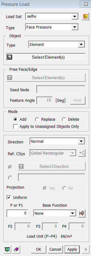
<Pressure Load>
Load Set
Select
a Load Set in which the specified load is included
Click ![]() to the right to
prompt the Define Load Set dialog box to add, modify or delete Load Set.
If the user types the name of Load Set directly in the entry box, GTS
will automatically create the relevant Load Set.
to the right to
prompt the Define Load Set dialog box to add, modify or delete Load Set.
If the user types the name of Load Set directly in the entry box, GTS
will automatically create the relevant Load Set.
Type
Face Pressure
Pressure
loads will be applied on the faces of 2D or 3D elements.
Edge Pressure
Pressure
loads will be applied on the edges of 2D or 3D elements.
Object
Type
Select
a method for selecting a part where the loads will be assigned..
Surface
Select Surfaces on which the loads will be applied.
Element
Select 2D elements on which the loads will be applied.
Element-Face
Select
3D element faces on which the loads will be applied.
Mode
Add
Add new loads to the selected nodes
Replace
Replace the previously defined loads on selected nodes
Delete
Delete the previously defined loads on selected nodes
Apply to Unassigned Objects Only
When
adding new loads, this option applies loads only to unassigned nodes.
Direction
Select
the direction of the pressure loads to be applied.
Normal
Apply the pressure load in the normal direction of the selected object.
Ref.CSys.-Axis 1
Apply the pressure load in the first direction of the reference coordinate system.
Ref.CSys.-Axis 2
Apply the pressure load in the second direction of the reference coordinate system.
Ref.CSys.-Axis 3
Apply the pressure load in the second direction of the reference coordinate system.
Direction
Select
the load direction from a Datum or a Geometric Shape.
<For Ref.CSys.-Axis 1, 2, or 3>
Ref. CSys
Select
the coordinate system which becomes the reference for the load components.
Click ![]() button to the right
to prompt the Create/Modify
Coordinate System dialog box to add, modify or delete the reference
coordinate system.
button to the right
to prompt the Create/Modify
Coordinate System dialog box to add, modify or delete the reference
coordinate system.
<For Direction>
Two
options are available for defining the force direction. Check on the first
option to select a direction from Datum or Geometric Shape. The second
option is to define the direction vector directly.
Projection
When the pressure loads are applied to plate or solid elements in the direction of the reference coordinate system, select whether or not to project the loads on a plane perpendicular to the loading direction.
Yes
Project
the pressure loads
No
The
pressure loads are applied along the entire face
Uniform
The
pressure loads are uniformly distributed.
P or P1
Enter
the pressure load value. If it is not uniform, the pressure load value
is applied at the first node.
Base Function
If the pressure load is defined
using a function, select the relevant function. Click ![]() button to prompt the Create/Modify Function
dialog box.
button to prompt the Create/Modify Function
dialog box.
P2~P4
When the pressure load varies linearly, enter the pressure load values at each element node.