 Zoom All Zoom All
Zoom in/out to fit the whole model on the screen.
 Zoomfit Grid Zoomfit Grid
Zoom in/out to appropriately to fit both the
model and the work plane grid.
 Zoom Window Zoom Window
Zoom in to the designated rectangular area.
 Zoom in/out Zoom in/out
The user can click on the icon menu and use
the left mouse button or the mouse wheel to zoom
in/out.
Dragging right while holding the left mouse
button expands the model; dragging left shrinks
the model. Scrolling upward zooms in and scrolling
downward zooms out.
Holding the Ctrl key allows the user to expand
and shrink the model without having to select
the zoom in/out icon.
 Rotate Rotate
Click this icon menu and dragging the left mouse
button on the task window rotates the model in
the drag direction.
For continued rotation, hold the Ctrl key and
drag with the right mouse button.
 Rotate center Rotate center
Specify a reference point and rotates the model
around that point. In the work plane, dragging
with the middle mouse button held rotates the
model around the specified reference point.

 Pan Pan
Move the model to desired location.
In the work plane, dragging with the left mouse
button held moves the model in the drag direction.
Holding the Ctrl key and dragging with the middle
mouse button held allows the user to move the
model without having to ‘Pan’ icon.
 Normal Normal
Move the perspective in the normal direction
of the working plane. (Perspective changed to
a 2 dimensional view with the X-axis to the right
and the Y-axis to the top of the screen.)
 Isometric 1 Isometric 1
Change the perspective to the isometric view.
(Z-axis of the global coordinate system points
up.)
 Isometric 2 Isometric 2
Change the perspective to the isometric view.
(Y-axis of the global coordinate system points
up.)
When importing a geometric model created in
CAD, use this perspective to view the model in
the same perspective as CAD.
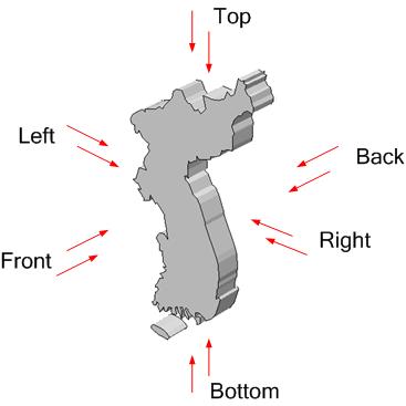
 Front Front
Change the perspective to the front view.
It is the Y, Z plane of the global coordinate
system rotated 180 degrees about the Z-axis.

 Back Back
Change the perspective to the back view. It
is the Y, Z plane of the global coordinate system.

 Top Top
Change the perspective to the top view.
It is the X, Y plane of the global coordinate
system rotated 90 degrees about the X-axis and
the Y-axis.

 Bottom Bottom
Change the perspective to the bottom view.
It is the X, Y plane of the global coordinate
system rotated 90 degrees about the Y-axis and
the X-axis.

 Left Left
Change the perspective to the left view.
It is the X, Z plane of the global coordinate
system rotated 180 degrees about the Z-axis.

 Right Right
Change the perspective to the left view.
It is the X, Z plane of the global coordinate
system.

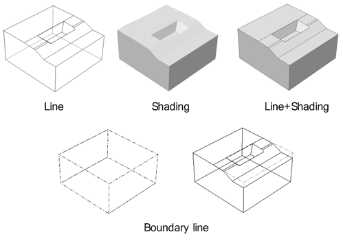
 Display mode [Geometric] :
Provides various view modes to display the model. Display mode [Geometric] :
Provides various view modes to display the model.
GTS NX provides various display modes that help
the user easily understand the work state and
display the model as they please.
The display mode can be called up by selecting
the geometric shape and clicking the right mouse
button.
Display the geometric
shape using faces and outlines.
Display the geometric
shape using only faces.
Display the geometric
shape using only outlines.
Display the geometry
object by its bounding box than its actual shape.
The user can change
the color of the object depending on the geometric
shape, mesh, material or other properties. The
user can define the color of the object directly
or randomly assign a color using the random color
assign function.

When
displaying the geometric shape using the [Shading]
or [Shading and line] method, the user can specify
the shading transparency to display the interior
of the object.
The transparency can
be specified by selecting the geometric shape
and clicking the right mouse button > Contents
menu > Transparency.
Complex geometric shapes
can be effectively represented by applying different
display modes to individual geometric shapes.
|


 Display
mode [Mesh]
Display
mode [Mesh]
 Perspective view
 Geometry shadow
 Bounding box