General
[General]
Application : Specify the user name,
company name, temporary file folder, file
save interval, etc. License : Authorize the program license.
The Stand Alone (USB Hard lock) method and
the Web Authorization method are supported.
Unit system : Specify the force/length/time
unit system used for analysis. Use the Unit
converter at the bottom right to convert the
units before or after analysis.
[Graphic]
- The mouse operation
can be used to fit the utilized 3D CAD wheel operation.
- The Smoothing Surface
Rendering method regulates the edge line tessellation
of a cylinder shaped curved surface. The available
levels are from 1 to 5, with a higher quality
and smoother surface as the level gets higher.
- The Shape of the
Dynamic View is the option for the displayed modeling
shape on the work window during view rotation.
Selection : Specify the options for
the model part. Guider : Specify the options for the
screen guider. Geometry shape : Specify the color for
each geometry shape type. Element : Specify the color for each
element type. Advanced : Adjust the advanced options
for the graphic setting. It determines whether
to show the shadow and controls its shade.
The available levels are from 1 to 5, with
darker information shown as the level gets
higher.
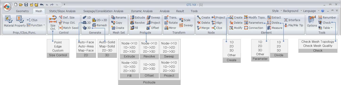
Geometry/Mesh/Connect
[Geometry]
[Mesh Set]
Load/Boundary Condition
[Coordinate system] : Specify the color of the
coordinate system symbol. Symbol 1, Symbol 2,
and Symbol 3 represent the X axis, Y axis, and
Z axis respectively.
[Mesh] : Specify the size of the node and element
number.
[Static load] : Specify the size and color of
the static load symbol.
[Dynamic load] : Specify the size and color
of the dynamic load symbol.
[Boundary condition] : Specify the color of
the boundary condition symbol.
Analysis/Results
[Analysis]
Number of processors : Specify the number
of CPUs used for analysis. For a dual core
CPU, input 2 processors and for a quad core
CPU, input 4 processors to increase the analysis
speed. Element Formulation : Specify the formula
applied to the element.
In terms of speed, a faster solution can be
obtained in order of Reduced (Efficiency)
> Standard (Stability) > Hybrid (Accuracy).
In terms of accuracy, a more accurate solution
can be obtained in order of Hybrid (Accuracy)
> Reduced (Efficiency) > Standard (Stability).
Equation Solver (Structural) : Specify
the method for solving a finite element simultaneous
equation. If the setting is automatic, the
program automatically determines one of the
following methods: Multifrontal, Dense matrix
or AMG(Algebraic Multi-Grid). 2D Element Setting (Structure) : The
[Unique Shell Normal Generation] function
judges two adjacent shell elements to have
two different normal directions when the value
between the normal direction vectors are larger
than the input value. Because the element
size is relatively larger than the curvature,
if this value is increased for a rough curved
mesh, a smooth contour that considers the
curvature of the geometry shape can be calculated.
The [Consider Drilling DOF(degree of freedom)]
option calculates the stiffness of the in-plane
deformation by considering the rotation about
the out-plane axis (drilling degree of freedom).
[Result]
General : Input an analysis result that
is extremely small and can be considered as
0. The default value is set as 1e-12, and
results lower than this value is considered
as 0. Contour : Determine the various settings
for contour representation of analysis results.
Vector : Display results that are represented
with a (V) using vectors. Here, specify how
to represent the vectors. Deform : Specify the basic settings
for checking the deformed shape of analysis
results. No result entity : Specify how to represent
the no result entities when displaying analysis
results. Diagram : Determine the basic settings
for diagrams. Graph : Select whether to show the graph. Animation : Specify the location in
which the animation image types and files
are saved. Legend : Specify the background color
and number of result bands displayed on the
screen.
Customize Shortcut
Key
The user can call up frequently used commands
by defining a shortcut key. |