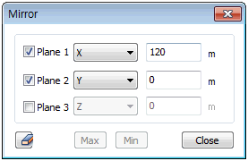
Symmetric
and inverse symmetric constraints
Boundary conditions can
be largely divided into two conditions;
1.
Constraint conditions of the analysis target are
specified
2.
Symmetry of the structure is used to analyze the
symmetric area only, not the entire model.
Applying
symmetry is a very effective way to increase the
convenience of modeling and decrease the analysis
time. If the geometry of the structure and loading
is symmetrical, a 1/2 model or 1/4 model can be
used to decrease the number of elements and create
an economic model that reduces analysis time.
However, constraints exist when checking the deformed
shape or stress distribution for the entire model
because the analysis results from the symmetric
model cannot be shown on the entire model. Here,
use the View symmetric model function on the Additional
view control toolset to expand the analysis results
of the 1/2 or 1/4 model onto the entire model.


If one or more of the
geometry shapes, materials, loads or boundary
conditions is symmetrical about a plane or axis,
the symmetric boundary condition can be used.
The View symmetric model function can output,
expand a 1/2, 1/4, 1/8 symmetric model onto the
entire model. To assign a symmetric boundary condition,
a boundary condition needs to be set such that
the structure does not invade the symmetry plane.
The
figure below is an example of symmetric constraint
conditions applied to a solid model. To apply
the symmetric constraint conditions in the YZ
plane, the Translation degree of freedom Tx is
constrained. For the XY plane, the Tz needs to
be constrained and for the ZX plane, the Ty needs
to be constrained.

Because Solid elements
do not have a rotational degree of freedom, only
the displacement boundary condition of the symmetric
model is constrained. However, the rotational
degree of freedom needs to be constrained for
a Shell model such that the symmetry plane is
not invaded. In other words, Tx,Ry,Rz need to
be constrained for the XY plane, Tz,Rx,Ry for
the XY plane and Ty,Rx,Rz for the ZX plane.
When
applying a symmetric boundary condition, the loading
size needs to be converted to fit the symmetric
condition. Also, the symmetric condition cannot
be applied to the model shape and buckling shape
because of the asymmetric vibration mode or the
possibility of asymmetric buckling. |


