|
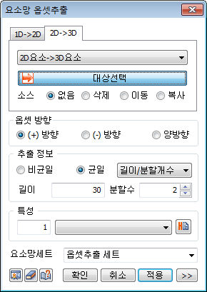
Select the 2D element or 3D element boundary surface and set the offset direction, extrude length and number of divisions. The element can be created by extruding in 1 direction or 2 directions. The original element (2D) used in extrude can be deleted/moved/copied. For move, the used element is moved to the end of the extruded element.
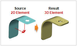 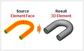
<2D element->3D Offset extrude> <Element face->3D Offset extrude>
Offset Direction
Set the extrude direction in the selected object [Possitive] direction (normal direction), [Negetive] direction (opposite normal direction), or in [Both] directions.
Extrude Information
Set the total width and division of 2D element will be created. The division spacing can be uniform or non-uniform. Entering a negative value for length (offset, spacing) extrudes in the opposite direction to the axis or vector direction.
[Non-uniform]
Specify the offset length and number simultaneously. The length can be listed using a comma (,) or as number@length for continuously repeating extrude operations.
For example, entering 10@3 creates 10 elements with a length of 3 each and entering 2,3,4 creates 3 elements, each with a length of 2,3 and 4.
[Uniform]
Set the offset length or number, or input the total length and division spacing.
|