Import
CAD File
Using the Import CAD File automatically deactivates
the analysis information of the current model.
The user can use this function even when a file is not
open and can import as many CAD geometries as they wish
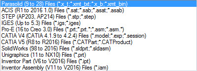
without limits. Parasolid (Parasolid(9 to 28) (*x_t;*.xmt_txt;*.x_b;*xmt_bin)
file formats and optional CAD file formats as below are
supported.
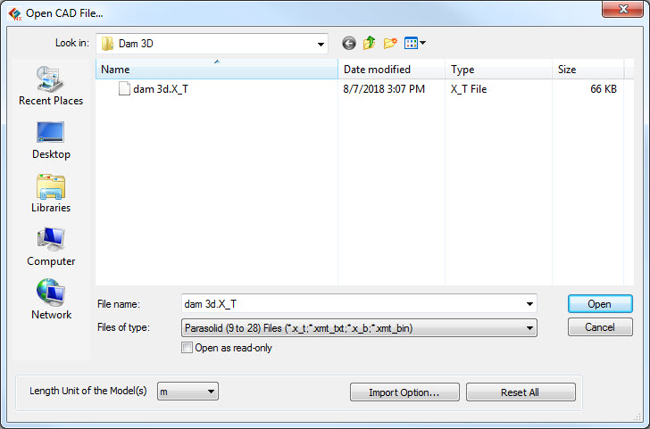
Because CAD geometries do not have a length unit, the
user must set the length unit when importing. The set
units decide the size of the CAD geometry and both the
meter and feet units are supported.

DXF
2D (Wireframe)
This function imports a DXF file created on a higher
version of AutoCAD than R13. The user can import 2D surfaces
as well as wireframes (a model consisting of edges).
DXF files created on AutoCAD do not have tolerance that
can determine the connectivity between endpoints. Although
edges may seem connected to the naked eye, they maybe
intersected or not connected after import. It is recommended
that the user check the edges of the AutoCAD DXF file
before importing.
<When the endpoints do
not coincide>
If a line is joined by multiple polylines, it may not
be imported properly. It is recommended that these lines
be exploded on AutoCAD before importing.
<Example of joined poly
lines>
When importing a 2D DXF file, the user can simultaneously
input distance from origin along x axis and y axis to
move or rotate about z axis the imported file in order
to place it at the desired location in the model.
Wireframes can be imported in GTS NX as a single composite
line for easy management or as individual lines.
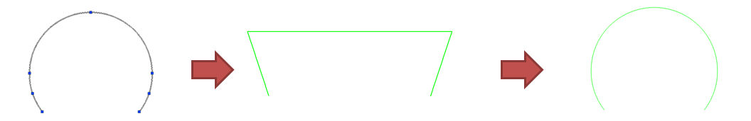
Imported intersected edges can be cut and registered
using the [Break Intersected Edges] function.
DXF
3D(Wireframe)
This function imports a DXF file created on a higher
version of AutoCAD than R13. It imports a 3D model on
to the work space. The user can call up DXF file as a
wireframe (a model consisting of edges).
DXF files created on AutoCAD do not have tolerance that
can determine the connectivity between endpoints. Although
edges may seem connected to the naked eye, they maybe
intersected or not connected after import. It is recommended
that the user check the edges of the AutoCAD DXF file
before importing
When importing a 3D DXF file, the user can simultaneously
input distance from origin along x axis, y axis and z
axis to place the imported file at the desired location
in the model.
Wireframes can be imported on to the GTS NX as a single
composite for easy management, or as individual lines.
Imported intersected edges can be cut and registered
using the [Break Intersected Edges] function.
Import
DWG
This function imports a DWG file created on a higher
version of AutoCAD than R13. It imports a CAD model onto
the 2D space or 3D space.
Like the Import DXF file function, DWG files created
on AutoCAD do not have tolerance that can determine the
connectivity between endpoints. Although edges may seem
connected to the naked eye, they maybe intersected or
not connected after import. It is recommended that the
user check the edges of the AutoCAD DWG file before importing
When importing a 2D DWG file, the user can simultaneously
input distance from origin along x axis and y axis to
move or rotate about z axis the imported file in order
to place it at the desired location in the model. While
when importing a 3D DWG file, the user can simultaneously
input distance from origin along x axis, y axis and z
axis to place the imported file at the desired location
in the model.
Imported edges can be registered on the geometry set
for each layer using the [Create geometry set for layers].
Execute
Mining Model Convert
/mining_model_convert/figure1.png) /mining_model_convert/figure2.png)
Mining data type: Type can be selected from
3D Face and Model Blocks. 3D Face type can import dxf.
file. Model Block type can import csv file.
Directory: Directory for information of model
file and define save folde.
Convert: It is creating the GT NX file(fpn.) after converting.
This converted file can be imported to GTS NX from Main
Menu > Import > GTS NX Neutral Format.
/mining_model_convert/figure3.png) /mining_model_convert/figure4.png)
[3D
Face] [Model
Blocks]
Import Midas Mxt file
Model information and loading/ boundary condition/analysis
data from the 'Gen, Civil, Building' program, other Midas
family programs, can be synchronized on the GTS NX. Element
types, load/ boundary conditions, analysis methods not
supported on the GTS NX are excluded.
The compatibility range for midas Mxt files is shown
below.
GTS |
Gen/Civil |
Restrictions |
Unit
System
Project
Setting
Node
Element
Mesh
Set
Material
Property
Supports
Point
Spring
Elastic
Link
Beam
End Release
Plate
End Release
Rigid
Link
Load
Set
Nodal
Mass
Self
Weight
Force,
Moment
Prescribed
Displacement
Element
Beam Load
Prestress
Pressure
Load
Nodal
Temperature
Element
Temperature
Temperature
Gradient
Response
Spectrum Function
Spectrum
Load Set
Time
History Function
Time
History Load Case
Dynamic
Nodal Load
Ground
Acceleration
Time
Varying Static Load
Time History Result
Function
Hinge |
Unit System
Structure Type
Node
Element
Group
Plastic Material, Material
Section, Thickness
Supports
Point Spring
Elastic Link
Beam End Release
Plate End Release
Rigid Link
Static Load Case
Nodal Mass
Self Weight
Nodal Loads
Specified Displacement of Supports
Element Beam Load
Pretension Load
Pressure Load
Nodal Temperature
Element Temperature
Temperature Gradient
Spectrum Function
Spectrum Load Case
Time History Function
Time History Load Case
Dynamic Nodal Load
Ground Acceleration
Time Varying Static Load
Time History Result Function
Inelastic Hinge Data |
Cable
→ Truss,
Wall → Plate element compatible, SRC excluded
PSC, Composite excluded |
Import
FPN file
This format links the model information file created
on Midas family programs (GTS NX, FEA, NFX, SoilWorks,
GeoXD) to the GTS NX.
This file format also enables user to exchange information
between different programs using text format.
Import
Nodal Results
This function allows users to import nodal results from
midas Gen and Civil into GTS NX.
Displacement results will be imported as prescribed
displacement (Tx, Ty, Tz).
Reaction results will be imported as nodal loads in
the opposing direction (FX, FY, FZ, RX, RY, RZ). |


 s
s/mining_model_convert/import.png)