Select
the 1D element, element side or edge to be extruded and
set the extrude direction, length and number of divisions.
The element can be created by extruding in 1 direction
or 2 directions. The original element used in extrude
can be deleted/moved/copied. For move, the used element
is moved to the end of the extruded element.
<1D
element->2D element extrude> <Element
edge->2D element extrude>
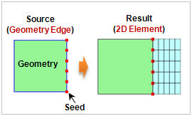
<Geometry
edge->2D element extrude>
Extrude
Direction
Select the element
extrude direction with reference to the GCS or input the
start and end points of the direction vector using the
2-point vector function. It is useful when extruding in
an arbitrary direction.
Extrude
Information
Set the total length
and division of 2D element will be created. The division
spacing can be set as either uniform or non-uniform. Entering
a negative value for length (offset, spacing) extrudes
in the opposite direction to the axis or vector direction.
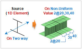
[Non-uniform]
Specify the offset
length and number simultaneously. The length can be listed
using a comma (,) or as number@length for continuously
repeating extrude operations.
For example, entering
10@3 creates 10 elements with a length of 3 each and entering
2,3,4 creates 3 elements, each with a length of 2,3 and
4.
[Uniform]
Set the offset
length or number, or input the total length and division
spacing.
The shape of the
2D element can be selected from a triangle or a quadrilateral
in advanced options ( ). ). |