Cutting
DiagramThe diagram setting method can be specified
as [Line] or [Surface], and the results can be
displayed as a diagram.
Cutting
Line
Select a 2-point
line or edge when defining the position. For the 2-point
line, select the coordinates directly on the
screen or input the coordinates of the 2 points. Then, specify the
direction of the diagram and input the number
of samples to divide the diagram by that number
and display on the screen. The diagram direction
follows the GCS and the default direction
is the (+) direction. To draw the diagram
in the opposite direction, check the [Reverse]
option. For the edge, select [Only On Node]
to draw the diagram on that node position.
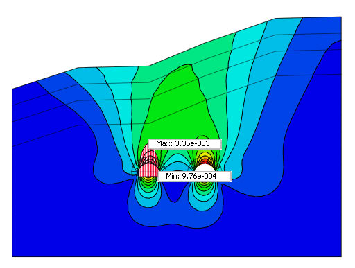
Only one edge can be selected. The arbitrary line
diagram is useful when assessing the relative
settlement conditions of a geotechnical structure
for 2D models.
Cutting
Plane
Select a 3-point
face or plane when defining the position. For the 3-point
face, select the coordinates directly on the
screen or input the coordinates of the three
points. The diagram direction
can be selected in the [Plane Surface] or
[Plane Normal] direction, and the [Reverse]
option can be checked to draw the diagram
in the opposite direction. The sample number
is the number of diagram divisions displayed
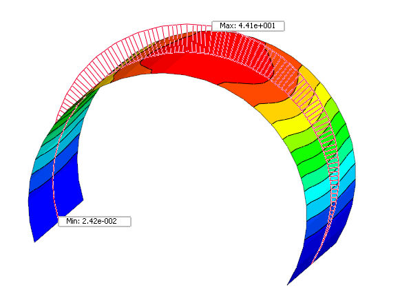
on the screen. The arbitrary plane
diagram is useful when checking the member
force distribution in a particular section
of a 3D model (ex. Lining transitional section
model). 2D elements like
shell or gauging shell can be directly selected
from this option to check for results.
|