Construction
stage analysis can be used to simulate the construction
process of the ground using numerical analysis. Construction
stage analysis consists of multiple stages and loading/
boundary conditions, as well as elements, can be added
or removed at each stage. This loading/ boundary or element
change is applied at the start of each stage. FEA NX can
use following types of analysis features to conduct Construction
stage analysis.
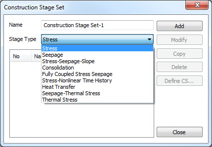
Stress-Slope Analysis
Analysis
of stress and slope stability during the construction
process
Seepage Analysis
Stage
by stage Steady state seepage analysis, Stage by stage
Transient seepage analysis
Stress-Seepage-Slope coupled analysis
Sequential
Seepage-stress analysis and Slope stability analysis during
the construction process
Consolidation analysis
Consolidation
analysis for environment change and construction process
of embankment
Fully-coupled Stress-Seepage analysis
Stress
analysis fully coupled with Transient seepage phenomenon
Stress - Nonlinear Time History
analysis
Users can perform nonlinear dynamic
analysis considering stress status of ground resulted
from not only self weight but also construction stage
(the history of stress).
Nonlinear
time history stage must be set at the final stage.
Heat Transfer
Stage by stage of steady state thermal
analysis, stage by stage of transient thermal analysis.
Seepage-Thermal
Stress
Users can perform thermo-hydro-mechanical
analysis.
Thermal
Stress
Thermo-mechanical
simulation can be conducted.
When
conducting Construction stage analysis, the following
should be considered.
Addition/Removal of element Loading/Unloading of weight Change in boundary condition Change in rock material
property Definition of load distribution
factor Step by step underground
water level Drained-Undrained analysis Initialization of displacement Stress Analysis for initial
construction stage (Consider Ko condition) Restart
For example, the construction
stages for a tunnel are as follows.
1
Stage: Initial ground stress
2
Stage: 1st face excavation
3
Stage: 1st reinforcement + 2nd face excavation
4
Stage: 2nd reinforcement + 3rd face excavation
5
Stage: 3rd reinforcement + 4th face excavation
……
(Repeat) ……
The
first stage is the used to calculate the in-situ stress
of soil strata. Because stress analysis of the ground
assumes the in-situ state to be the initial state, the
in-situ stress state needs to be calculated.
FEA
NX uses self-weight analysis to calculate the initial
in-situ stress.
Activate / Deactivate element
An
element activated during Construction stage analysis has
a default in-situ stress value of ‘0 (zero)’. But if a
prestress is defined on the element, the element has the
defined prestress value as its in-situ stress. If the
self-weight is defined, the activated element has a body
force due to its self-load. If the activated element uses
the Modified Cam-Clay material model, it has an initial
linear-elastic property that is determined by the loading/
boundary conditions of the corresponding stage.
New
nodes will be activated as the element appears, and the
initial displacement of the node is also ‘0 (zero)’.
If
an element is deactivated at a construction stage, and
an additional load distribution factor is not defined,
the internal forces of the deactivated element are no
longer considered. The total stress state is re-distributed
according to this condition.
Loading / Unloading of weight
The
addition and removal of load at each construction stage
is possible and the load from the previous stage is maintained,
except for following cases.
When an element subjected
to the load is deactivated at a stage, its self-weight
and external load applied to it are also removed. When a node subjected
to the load is deactivated, the external load applied
to it is also removed.
Added
load is cumulated to the already applied load from the
previous construction stage.
Boundary
conditions can also be modified in the same way and the
same exceptions hold true.
Load distribution factor
The
Load distribution factor is used during Construction stage
analysis to simplify the modeling. The Load distribution
factor is a numerical analysis method that uses the load
distribution factor to apply the effects of element removal
sequentially in the following stages. The Load distribution
factor can be used to simplify a 3D problem in 2D, or
to downscale the construction stage of a 3D model during
analysis.
For
example, if stress relaxations of 40%, 30% and 40% are
assumed to occur in three consecutive stages, starting
from the excavation stage, define the excavation stage
and activate the load distribution factor option for that
step. Input 0.4, 0.3 and 0.3 for the load distribution
factor in option window for ‘After Current Stage 0, 1,
2 stage’ respectively.
Material property conversion
During
Construction step analysis, the ground material properties
can change to model time dependent ground disturbance,
soil improvement or hardening. There are also cases where
the structural material properties need to be change in
the middle of the stage, such as hardening of lining concrete
or changes in lining thickness. For this purpose, the
material properties of a specific element can be changed
without any number limits. The changed material property
is continued onto the element results(displacement, stress,
strain etc.) of the previous stage for analysis.
Caution:
The Material property conversion feature needs to be used
carefully. Changing the infill material after excavation
in Construction stage analysis can be simulated using
just the property conversions, without activating or deactivating
any elements. Here, the stress conditions from the previous
stage is applied to the following stage and so, physically
inappropriate behavior can be observed due to the material
property conversion. Hence, the material property conversion
needs to be conducted at a stage where the element is
deactivated and re-activated to obtain the intended results.
If a new element is activated, the internal element has
an in-situ stress, strain and interior state variable
of ‘0(zero)’.
Undrained Analysis
Undrained
analysis can be conducted for selected elements and selected
construction stages. Two conditions should be satisfied
beforehand to apply undrained analysis. Firstly, the drainage
parameter should be set as undrained type on material
model. Secondly, the undrained condition should be checked
on the Analysis control of construction stage. If only
one of the conditions is met, the material conducts drainage
analysis in the corresponding stage.
For
singular analysis cases such as static linear/nonlinear
analysis, or slope stability examination, check the Analysis
Control > Undrained Condition > Allow Undrained
Material Behavior. |
