|
Consolidation (singular) analysis, Stress seepage-Fully coupled – Loading/Sustain
Specify the applied time step and load factor. In consolidation analysis, the analysis can be simulated using 'Sustain' option without creating the construction stage. User can define loading and leave time separately.. All applied loads including self-weight is used for analysis, according to the input time and load factor. The analysis is conducted by simulating the dissipation of excess pore water pressure in the lead load stage, according to the defined time information, after the [Loading] analysis has finished. Because of this, the load factor in the [Sustain] cannot be input and the time information is added to the final time of the [Loading].
Construction stage consolidation analysis - Input time and load
For consolidation analysis, the appropriate load application time and load distribution of an added load can be done by inputting the time and load factor.
<Initial state> <Embankment load application> <Sustained period>
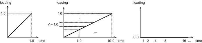
<Initial state> <Embankment load application> <Sustained period>
When using a Modified Cam-clay material model, the in-situ stress needs to be defined. Hence, drainage analysis is needed to calculate in-situ stress and in this case, the application time is meaningless.
If an additional load is applied, the load is applied over an appropriate total time, as shown in the ‘Embankment load application’ figure above. The figure displays the additional load applied in 10 equal stages over 10 days. Here, the sum of the load factors is 1.0.
After the embankment has finished, the leave analysis can be conducted where the load is left continuously without any additional increase. The leave time is defined as shown in the ‘leave period’ figure above. Because of the characteristics of consolidation analysis, the initial stress change happens rapidly. Hence, the first time step can start as small and gradually increase with time to pursue both convergence and analysis speed.
Seepage(Transient analysis) - Define time step
Specify the time step for performing analysis and saving results. The seepage boundary time function value (heat, flow rate etc.) that corresponds to the set time step is used for analysis, and the results can be examined. Values outside the time range of the seepage boundary time function can be automatically applied using linear interpolation.
Dynamic analysis - Define time step
It is possible to assign time step using irregular intervals and so, the target time step is assigned a name.
-
Time Duration : Insert the time interval
-
Time Increment : Input the time interval that will be used for calculation for the entered time range.
-
Intermediate Output : Input the time interval for the output of analysis results. The results are printed for every time interval x print interval for interim results.
※ At every assigned interval, a result is printed on the result tree. If you need to print out any amount of data, it might take a considerable amount of time. In case your PC is lack of RAM, the result file might not be created.
According to the assigned time step, it shows total amount of time elapsed (total amount of time used for analysis according to the time step), the total number of time step (The total number of time steps used during the analysis).
|
