|
 Pick/Rectangle select Pick/Rectangle select
Sets the mode to select the specified object
 Unselect mode Unselect mode
Sets the mode to unselect the specified object
Select screen
Selects/Unselects individual objects or objects within an area set by dragging the mouse. There are four ways to select an area; rectangular, ellipse, polygon and polyline.
-
 Rectangle (Pick/Window) Rectangle (Pick/Window)
Select/unselect all current selected objects.
Individual objects or objects within an area set by dragging the mouse can be selected or unselected.
The ‘Pick’ and ‘Window’ are distinguished only by mouse click or mouse drag.
[Pick Select]
Select/unselect objects by individual clicks.
In the select mode, an already selected object can be unselected by selecting pick again.
[Window Select]
Select/unselect objects within a rectangular area created from a diagonal movement by mouse drag.
The Esc key cancels the definition of the rectangle during mouse drag.
*The direction of the mouse drag during Window Select is not important. To include/exclude objects is determined only by the Include Intersected option.
-
 Circle Circle
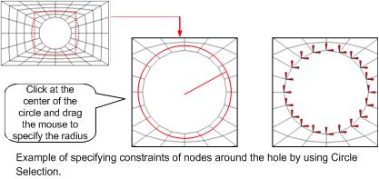
Select/unselect objects within a circular area.
The area is defined by a left mouse click at the center of the circle and a mouse drag that determines the size of the radius. The Esc key cancels the definition of the circle during mouse drag.
-
 Polygon Polygon
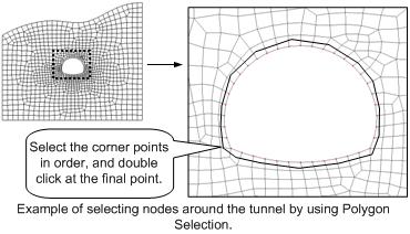
Selects/unselects objects within a polygon.
The polygon is defined by clicking consecutive points and double-clicking the left mouse button at the final point. The area is defined by the connected start and end points.
Clicking the right mouse button cancels the definition of the polygon.
-
 Polyline Polyline
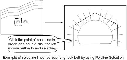
Selects/unselects objects intersected by a polyline.
To define multi-line, the user can specify the polyline by clicking consecutive points and double-clicking the left mouse button at the final point. Clicking the right mouse button cancels the definition of the multi-line.

Selection filter
The Selection filter primarily filters the selected objects by their specified types.
The Selection filter is composed of an object type predetermined by the current work status and the summoned command types. The user can specify a particular object type in this configuration.
The Selection filter-related work status is basically classified by the command execution viability.
-
 Main selection filter Main selection filter
Sub selection filterThe Main selection filter has the most basic default composition.
Only geometric elements (sub-objects not selected), mesh sets and datum registered on the shape set can be selected in the Main selection filter.
*The datum is the reference point, axis, or plane for modeling.
-
 Sub selection filter Sub selection filter
The Sub selection filter is restructured into types based on command execution viability.
Geometric elements registered in the shape set can be selected, as well as the sub-objects of the shape (point, edge, face etc.), loadings, boundaries and individual joints and elements.
*Because the selection filter composition is different for every command, it is recommended that the user check the select filter composition when using a command for the first time.
|

|
Shape
|
Type
|
|
F-1
|
Face (Four subdivision Edges)
|
|
E-1
|
Edge
|
|
Shape
|
Selection filter
|
Selectable objects
|
|
Face
|
Main selection filter
|
1 (F-1)
|
|
|
Sub selection filter
|
1 (F-1)
|
|
Line
|
Main selection filter
|
1 (E-1)
|
|
|
Sub selection filter
|
5 (E-1, E-a, E-b, E-c, E-d)
|
<Table. The selection difference between the Main select filter and the Sub select filter>
The Selection filter composition is as follows.
|
Selection filter
|
Selectable objects
|
|
Data axis (X)
|
Select the data axis.
4Used to specify the direction (Translate/Extrude/Project), rotation axis etc.
|
|
Data plane (U)
|
Select the data plane.
4 Used to specify the work/reflect/divide/mirror plane etc.
|
|
Geometry related
|
|
All geometric shape (P)
|
Select the “Shape”, the highest ranking geometry.
|
|
Solid (D)
|
Select a solid.
|
|
Shell (J)
|
Select a shell.
|
|
Face (A)
|
Select a face.
|
|
Wire (W)
|
Select a wire.
|
|
Edge (G)
|
Select an edge.
|
|
Point (B)
|
Select a point.
|
|
Complex object (C)
|
Select a complex object.
|
|
Mesh set / joint / element related
|
|
Mesh set (M)
|
Select a mesh set
4 Used to select a mesh set itself or the joints and elements in the mesh set.
|
<Table. Selectable elements in the Main selection filter>
|
Geometry related
|
|
Face (F)
|
Select a face, a lower ranking geometry of the "Shape".
|
|
Line (E)
|
Select a line.
|
|
Point (V)
|
Select a point.
|
|
Load/Boundary (L)
|
Select the load/boundary conditions applied on the geometry.
|
|
Mesh set / joint / element related
|
|
Node (N)
|
Select a node.
|
|
Element (T)
|
Select an element.
|
<Table. Selectable elements in the Sub selection filter>
 Difference in selection between the Main selection filter and the Sub selection filter Difference in selection between the Main selection filter and the Sub selection filter
The user may be unfamiliar to the difference in selected objects between the Main selection filter and the Sub selection filter, where only the highest ranking geometry “Shape” is selected for the Main selection filter, but this function is useful during modeling.
The following example will explore the convenience of using the Main selection filter.
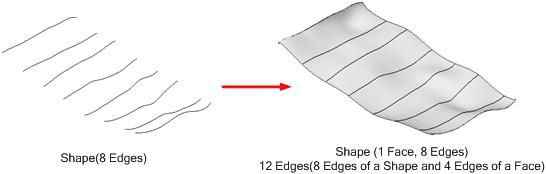
The figure below shows a Face, interpolated by Edges created from the cross sections of a random 3-dimensional curved face.
To hide (or remove) the eight Edges that are no longer useful after the face has been created, let us consider case when only the eight Edges are selected.
-
When the selection of all geometry is allowed in the Main selection filter (not just "Shape")
When using the [Rectangle selection] with the selection filter set at 'all geometric shape', nine "Shapes" (one Face, eight Edges) are selected.
-
When using the [Rectangle selection] with the Main selection filter set at <Edge>
A total of twelve Edges are selected, four of which are the lower rank Edges of the Face and cannot be hidden individually.
*Manual selection is possible, but because the “Shape” Edges and the lower rank Edges of the Face exist in the same position, it is not easy to manually select individual edges.
-
When allowing only the “shape” selection in the Sub selection filter
When using the [Rectangle selection] with the selection filter set at <Edge>, the eight Edges can be easily selected and can be hidden directly.
*In practical use, the user can take advantage of the work tree to make this work much easier.
Thus, the Main selection filter and Sub selection filter are separated to provide convenient selection during actual work.
Selection filter use
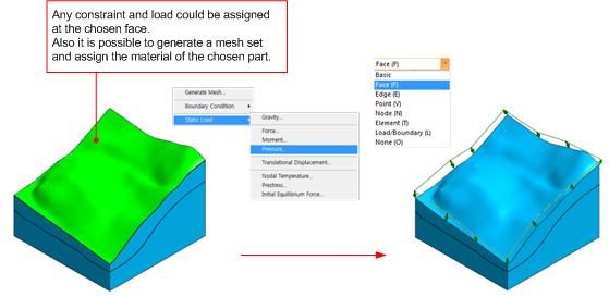
Command execution mode using the Sub selection filter
The direct constraints and loading conditions can be defined on the work screen using Sub selection filters. Also, the parts can be specified as selection elements, making it possible to assign materials or mesh sets. The Sub selection filter selects the sub-objects of a shape (point, edge, face etc.), as well as joints and elements. Application of the Sub selection filter on the work screen helps the user easily define properties using geometric features without a separate command execution mode process.
* To select nodes or elements based on geometric shapes, the object must be shown on the screen.
Specifying the direction and axis of rotation
Setting the direction for Translate, Extrude or Project, as well as the axis of rotation for Rotate and Revolve, is often needed during the modeling process. In this case, the direction and axis of rotation can be specified by various methods using the Datum and the geometric features of the shape.
The following is a summary of the methods used to specify the rotation axis direction.
|
Available object
|
Used geometric features
|
Selection filter
|
|
Datum axis ①
|
Direction of Datum axis
|
Datum axis
|
|
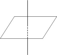
Datum plane
|
“Normal” direction to the Datum Plane
|
Datum plane
|
|
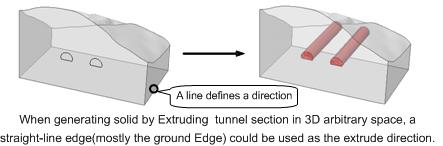
Edge (Straight line)
|
Direction of straight line
|
Edge
|
|
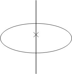
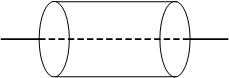
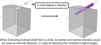
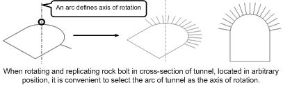
Edge (Circle or arc)
|
“Normal" direction to the plane where the circle/arc and its center point exist
|
Edge
|
|
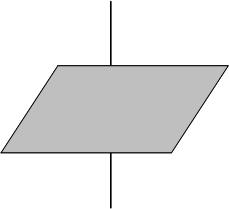
Plane surface
|
“Normal” direction to the plane
|
Face
|
|
Rotated body face
|
Central axis of the rotated body (cylinder etc.)
|
Face
|
|
2 point vector
|
User specified 2 point vector
|
N/A
|
|
Normal line to the profile ②
|
"Normal" direction to the Profile, whose "plane" definition allows Extrude etc.
|
N/A
|
①The selection filter for specifying direction, axis of rotation is fundamentally set as <Datum axis>.
②This is only restrictively supported for some functions such as Extrude.
The use of such selection methods that utilizes the geometric features of objects allows the convenient specification of direction and axis of rotation, even for very complex models.
Selection using the concept of hierarchy for geometric shapes
When selecting lower rank objects using the concept of hierarchy, selecting a higher rank object provides the selection functions for all lower rank objects (sub-objects that correspond to the type in selection filter) within it.
In the figure below, the lines need to be selected individually when the Sub selection filter is set as Edge (E). However, setting the Sub selection filter as a Face (F) and selecting the face selects all 4 lower rank lines.
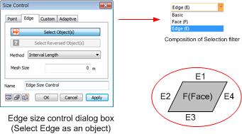
In other words, when selecting all the lower rank objects in a particular object, it is convenient to select the higher rank object first and then set the [Sub selection filter] to that higher rank object type.
Node, Element Selection
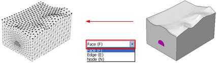
Similar to the concept of hierarchy, when selecting nodes or elements, setting the selection filter to Mesh Set (M) and selecting the Mesh Set selects all the nodes and elements within the mesh set.
If the mesh is created on a geometric model, the user can choose the nodes and elements based on the geometric shapes (line, face) that form the mesh.
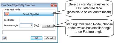
Free face / free end-node selection function using the feature angle for nodes and elements
The loading, boundary condition dialog box provides additional functions that consider individual loading and boundary conditions for easier selection.
The most useful selection functions are for the adjacent Free Face of a 3D element and adjacent Free End of a 2D element.
 Select all neighboring edges or surfaces Select all neighboring edges or surfaces
Automatically selects adjacent elements (faces/lines) after selecting a face or line.
 Select neighboring edges or surfaces with feature angle Select neighboring edges or surfaces with feature angle
Automatically selects adjacent elements (faces/lines) within the feature angle after selecting a face or line.
 Limit feature angle Limit feature angle
Limits the feature angle for selecting adjacent lines or faces.
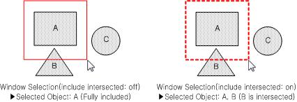
 Intersect Intersect
This function selects objects that are within the borderlines of an area created by a rectangle, circle or polygon.
*The borderlines of the area are displayed in dotted lines for the Intersection selection function. Pressing and releasing the Ctrl key when drawing the rectangle, circle or polygon switches to the Intersection selection option.
 Front selection only Front selection only
Selects only the objects at the front in the current view. It is used when the object consists of multiple layers and the user wants to select one face.
 Select all Select all
Selects all objects in the current work space.
In the view all perspective, all objects in the current work space are selected.
 Unselect all Unselect all
Unselects all objects in the current work space.
In the view all perspective, all objects in the current work space are unselected.
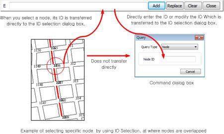
 Select node/element by ID Select node/element by ID
This function selects/unselects objects by entering the ID in the node, element select mode.
This selection method can be coupled with other selection methods. The node or element select mode is significant when the selection filter is set as "Node (N)" or "Element (T)" and can only be used in the node, element control functions (functions that require direct selection of the node/element). When ID selection is called up, a dialog box appears on the upper right corner of the work screen and the selection process is as follows.
-
Select individual nodes and elements by directly entering their ID in to the ID selection dialog box.
-
Selecting nodes and elements using other methods (Pick/Window, Circle etc.) in the work-plane transfers the node/element ID in to the ID selection dialog box. The user can check the transferred ID and edit to select the desired nodes and elements. It is useful to use the ID selection function when selecting some of the overlapping nodes or elements.
*The ID selection dialog box acts as a middleman between the Selection manager and the Command dialog box.
IThe ID selection dialog box buttons are as follows.
|
Add
|
Adds a new node, element ID to the selection.
|
|
Change
|
Releases all of the existing selection and only selects the nodes, elements with new ID. (Select substitution)
|
|
Delete
|
Deletes all content in the ID field.
|
|
Close
|
Closes the ID selection dialog box.
|
*When selecting new nodes, elements from the work-plane after deleting all content in the ID field, the existing selection is still shown in the ID selection dialog box.
|

