|
Sew
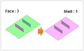
Combine independent faces (shell, face) into one shell. This function is used when the faces (shell, face) meet at the boundary edge with no overlap.
[Tolerance]
The allowable limit used in the Sew operation. If the gap between the face outlines is less than the tolerance, it creates a single shell without a free edge.
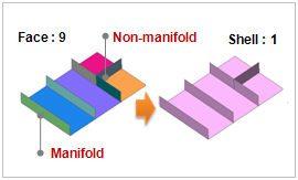
Checking the [Non-Manifold] option sews non-manifold faces that have three or more faces meeting at a single edge. Uncheck the option to not fuse Non-manifold faces.
Checking the [Make Solid] option automatically changes a perfectly closed shell into a solid.
Press the preview button [ ] to see the results of the Sew operation on the selected shape (shell, face). The areas displayed in dark red lines are the B-Spline sections that have not undergone the sew operation because they are not within the allowable limit. In this case, gradually increasing the limit and previewing the results repeatedly can prevent B-Splines from being displayed. Pressing the confirm or apply button with the B-Spline included creates a shell with a B-Spline included. ] to see the results of the Sew operation on the selected shape (shell, face). The areas displayed in dark red lines are the B-Spline sections that have not undergone the sew operation because they are not within the allowable limit. In this case, gradually increasing the limit and previewing the results repeatedly can prevent B-Splines from being displayed. Pressing the confirm or apply button with the B-Spline included creates a shell with a B-Spline included.
Be aware that a very large tolerance can create an abnormal shape.
<When fuse does not occur even with tolerance adjustment>
-
Check to see if the face overlaps at that position.
-
If a face is not sewed, sew the other faces first and then reconstruct the edges of the un-sewed face for another sew operation.
-
It is possible to perform the sew operation without removing a local B-Spline. In this case, a seed is assigned to the B-Spline to create a mesh and the fuse node operation is performed in the subsequent mesh creating process.
-
Modify the faces such that adjacent faces meet at the edges with the same length using Geometry > Surface&Solid > Merge Face-Edge. If a mesh is created with the same mesh size without fuse, the positions of the nodes are very similar. This process combines all the shared nodes of the created mesh into one using the merge node function.
Some faces are not shaded after the sew operation. This happens when there are problems in a face's configuration that create erroneous relationships with adjacent faces in the sew process, resulting in an incorrect shell. These errors can be corrected by modifying the incorrect face and then performing the sew operation. If there are problems after the suturing, the incorrect face can be removed from the shell by using the sub-shape remove function.
|