표시 

Home > FEA NX > Geometry > Divide > Surface


Surface


Overview

IMG_C_ICON_DOT.gifDivide multiple faces using arbitrary lines or faces.


Methodology

By Curves


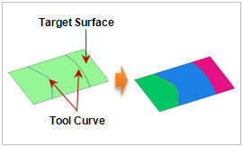
Select the target surface (shell, face) and the tool curves for division. If the tool shape consists of multiple edges, it is recommended to merge the edges into a single edge instead of selecting multiple edges.

If the tool curves do not exist in the same plane as the target surface, the tool edge is projected onto the target surface and then divided. In this case, the projection direction needs to be specified. The direction can be set in the following 4 ways:

1. [Projection Direction] : Determine the projection direction vector of the tool edge. The user can select the datum axis, datum plane, plane or edge.

2. [2 point vector] : Determine the direction vector by entering the coordinates of its Start and End points. The user can also directly click on the work screen to specify the Start and End points.

3. [Point on Curve] : Project an arbitrary point on the tool edge in the shortest distance direction to the target surface. The arbitrary point can be specified by a ratio of 0 to 1 from the Start point to the End point of the tool edge.

4. [Direction of Shortest Path Line] : Project in the shortest distance direction from the tool edge to the target shape.


Separate divided faces

Check this option to separate the shell into face units.

By Surface


Select the target surface (shell, face) and the tool faces for division. The tool faces can be directly selected or an infinite tool face can be created by defining the coordinates of three points.


Divide Touching faces

When multiple solids are adjacent with faces in contact, diving parts of the solid can also divide the adjacent solid and their contact face. This allows the sharing of face nodes when creating a solid.


Delete Original, Delete Tool

Check this option to delete the original target shape and tool shape after the division operation.


Geometry set

Register the created face on the Geometry set. The user can specify the name of the Geometry set.


IMG_C_ICON_NOTE_01.png

When working with an imported geometry data file, the shape may not divide well. The methods for dividing a face with a line are as follows:

  • When the tool line cuts across the target shape completely, it has a similar effect as the imprint operation.

  • Create a temporary solid by extruding the target surface using an arbitrary value and create a temporary face by extruding the tool curve. Dividing the created solid by using the created face leaves only the desired face. Using the sub-shape extend command deletes the temporary solid and the face.