|
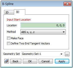
3D
Input the coordinates of the start point and the end point to create a B-Spline. The start point input is in the absolute coordinate(x,y,z) form. For the end point, the user can select one of the following 3 methods.
[Absolute(x,y,z)] : Input a 3D absolute coordinate value in the workplane.
[Relative(dx,dy,dz)] : Input the relative 3D distance from the point entered in the previous step.
The user can click on the workplane or a geometry shape and directly assign the next point, but because the workplane is two-dimensional, the y-axis values are not entered. The right mouse click stops further interpolation and creates the B-Spline.
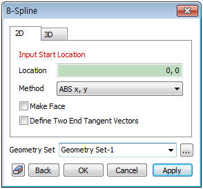
Make Face
Create a plane that has the closed B-Spline as its boundary.
Define Two End Tangent Vectors
Use the tangent vectors of the start and end points to modify the shape of the overall B-Spline after it has been finished.
Geometry set
Register the created B-Spline on the geometry set. The user can specify the name of the geometry set.
|