|
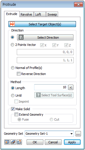
Input the geometry shape (face, line, point) for the Extrude operation and enter the extend direction and length. The extend direction can be set using the following 3 methods:
1. [Select Direction] : Determine the extend direction vector of the selected section. The user can select the datum axis, datum plane, plane or edge.
2. [2 point vector] : Determine the extend direction vector by entering the coordinates of its Start and End points. The user can also directly click on the work screen to specify the Start and End points.
3. [Normal of profile] : Extend the section in the normal direction to the plane when the direction can be specified. If there are multiple sections, the shape is extended for each normal direction. If the extend section is a curved face or a straight line, the normal direction cannot be defined and it cannot be extended.
Check the [Reverse Direction] option to reverse the extend direction.
[Length]
If the extend direction has a finite length (straight line edge or two-point vector), click the right "<" button to automatically enter the extend length.
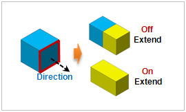
Make Solid
Used on solids created by a closed line. Using an open edge or wire does not cause errors, but be aware that it may create an incorrect shape..
[Fuse]
Use the Fuse operation between solids to expand the shape during extend process.
[Cut]
Use the Cut operation between solids to divide the shape during the extend process.
Geometry set
Register the geometry shape created from the extend line command on the Geometry set. The user can specify the name of the Geometry set.
|