|
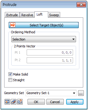
Select shapes to perform loft. The selection method depends on the selection order. The order can be largely divided into [Creation], [Selection] and [Vector].
[Creation] : Select section shapes in order of connection to create a shape. The selection shapes are selected individually with the mouse.
[Selection] : Select section profiles in order of connection to create a shape. The section profiles are selected individually with the mouse.
[Vector] : Select multiple sections that are connected depending on the organized vector direction of the object shape. 2 point vectors can be used to define the coordinates of the direction vectors at Pt1 and Pt2. The reference point and order of the profile is applied in the same way as organizing a section profile using the coordinate system.
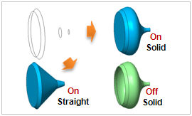
Make Solid, Straight
Check the [Make Solid] option to create a solid using a closed line.
Using this operation on an open edge or wire does not cause errors, but be aware that it may create an incorrect shape.
Sections with the [Straight] option checked on will connect each selected section using straight lines, not curved.
Geometry set
Register the geometry shape created from the loft extend command on the Geometry set. The user can specify the name of the Geometry set.
|