|
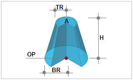
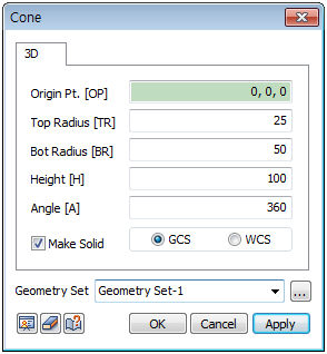
Create a cone from the Origin point (OP), Top Radius (TR), Bottom Radius (BR), Height (H) and Angle (A) input.
[Origin Point (OP)]
The center point consists of the Center point coordinates at the bottom face of the cone. The user can directly specify the center point of the workplane or geometry shape by selecting with the mouse. Because the workspace is 2-dimensional, the y-axis value is not entered.
[Angle (A)]
The angle is the rotation angle of the circle between the top and bottom face of the cone. If the user enters 360, it creates a generic cone with circular top and bottom faces.
Make Solid
Check this option to create a solid type cylinder with a volume. Un-checking the option will create a shell type cylinder.
Enter the center coordinates with reference to the Global coordinate system. In this case, the center coordinates are input in 3D space.
Enter the center coordinates with reference to the Workplane coordinate system. In this case, the center coordinates are input in 2D space.

For GCS (Global coordinate system) and WCS (Workplane coordinate system), please refer to General information-Manage modeling toolset.
Geometry set
Register the created cylinder on the Geometry set. The user can specify the name of the Geometry set.
|