|
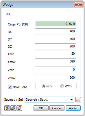
Create a wedge shape from the Origin Point (OP), Length (DX, DY, DZ) and Shape width (Xmin, Xmax, Zmin, Zmax).
The Origin Point (OP) is the corner point coordinates of the bottom face of the hexahedral. The user can directly specify the center point of the workplane or geometry shape with the mouse. Because the workspace is 2-dimensional, the y-axis value is not entered.
DX, DY, DZ represent the bottom face x direction length, height and bottom face width of the hexahedral respectively.
X min, X max is the relative distance of the Start and End point coordinates of the top face in the x-axis.
Z min, Z max is the relative distance of the Start and End point coordinates of the top face in the z-axis.

The hexahedral is created as follows. If the Corner coordinates are (X,Y,Z), The bottom face is the rectangle that starts at (X,Y,Z) and ends at (DZ,DY,DX). The top face is the rectangle that starts at (X+X min,Y,Z+Z min) and ends at (X+X max,Y,Z+Z max). The hexahedral is set based on the two rectangles.
Make Solid
Check this option to create a solid type cylinder with a volume. Un-checking the option will create a shell type cylinder.
Enter the center coordinates with reference to the Global coordinate system. In this case, the center coordinates are input in 3D space.
Enter the center coordinates with reference to the Workplane coordinate system. In this case, the center coordinates are input in 2D space.
For GCS (Global coordinate system) and WCS (Workplane coordinate system), please refer to General information-Manage modeling toolset.
Geometry set
Register the created cylinder on the Geometry set. The user can specify the name of the Geometry set.
|