|
The interface can be created using the following methods, depending on the work environment and comp1nts or shape.
<Line Interface> <Shell Interface> <Plane Interface>
Create an interface element at the boundary position between the selected element and adjacent element, as shown in the figure below. Selecting all elements cannot create an interface element because there are not adjacent elements. If the created interface element is within a mesh, the interface element has a wedge shape, as shown.
<From element boundary>
Directly input the node ID to create an interface element. The nodes are divided into 2 groups: Side 1 and Side 2 that determine the shape of the interface element. The number of input nodes on Side1 and Side2 must be the same and the shape for each size is as follows.
Convert a general 1D, 2D, 3D element into an interface element. Because general elements do not have a consistent node order, the base reference node needs to be selected additionally.
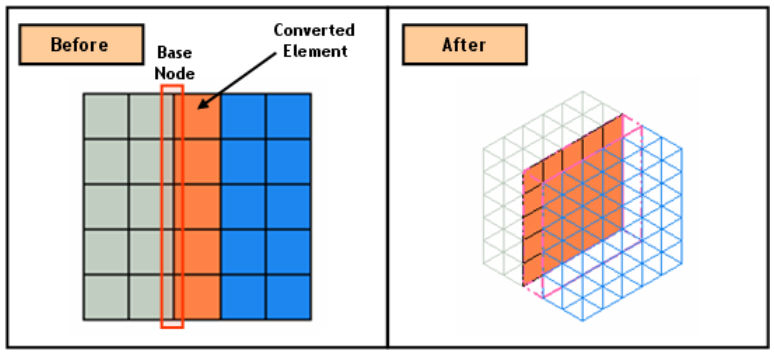
<Convert element>
Create an interface element from opposing free surface/edge. The free edges (free surface for 3D) with no node connections need to be selected on each side and if the free edge (free surface) does not exist, use the Connection > Divide function to divide beforehand.
Create an interface element using the truss/beam element. For 3D, use a plate element. Creating an interface element for structural elements such as truss/beam/plate generates an interface element on both sides of the element. Hence if the interface creation method is truss/beam, set the “add mesh set separately” option for the interface element to separately create the interface element in each direction.
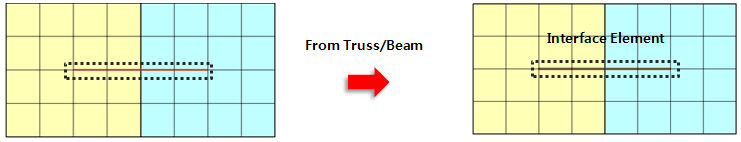
<Use structural element>
Also, if the ground element connected to the interface element is removed during construction, the interface element is also removed to prevent analysis errors.
The interface elements are created at the location where truss/beam elements cross T or X-shape. Shell elements can be selected in 3D model. The ‘Register Interface Mesh Set Separately’ option isn’t available since interface elements are T or X-shape.
<From Truss/Beam (T/X-cross type)>
Create an interface element at the T- or X-cross of the selected mesh set. This method can be used when the interface elements intersect, such as in masonry structures.
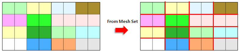
<From Mesh-Set (T/X-cross type)>
Create an interface element between adjacent elements, using the relationship between the selected nodes. For 3D, select a segment point if the interface element is not created properly.
|