|
Embedded trusses or Pile elements are interface elements that do not require node connections with neighboring ground elements. These elements can set independent mesh sizes or number of divisions to generate meshes independently.
The assigned properties can be set or new properties can be added during Mesh creation.
[Orientation (Element Z-Axis)]
This function is used to unify the direction property of a 1D element to 1 direction or to set the major and minor axes directions. Adjust the Z axis direction by checking the element coordinate axis and assigning with reference to the Beta angle.
-
Reference node: Select the reference node for the sectional direction of the 1D element. The element Z coordinate direction is set with reference to the selected node.
-
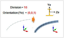
Reference Vector (GCS): Set the Z coordinate direction of the selected element using the GCS direction or the input vector direction.
-
Beta Angle: Angles 0, 90 and 180 can be chosen, and the selected Beta angle rotates the element by that angle with reference to the X axis.
<Beta angle:0> <Beta angle:90> <Beta angle:180>
Advanced Option ( ) )
Small gaps within the tolerance can be automatically joined for mesh creation. When creating a mesh for 2 or more edges, individual independent mesh sets can be generated.
|