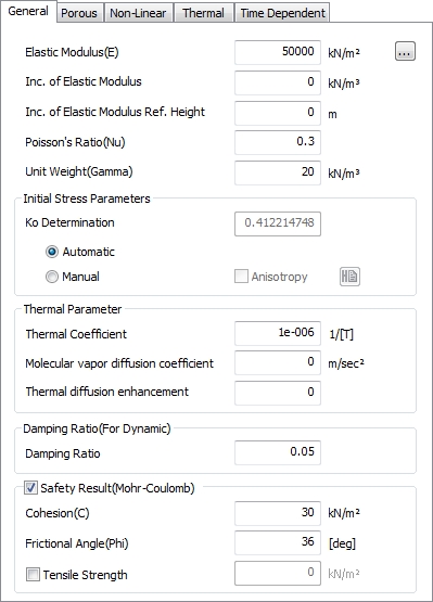
Default parameter (General)
The
input parameters and units for defining the default stiffness
and initial condition of each model are listed in the
table below
Input parameter |
Definition |
Unit |
Elasticity modulus( ) ) |
Elasticity
modulus |
kN/m2 |
Elasticity modulus increment |
The Elasticity
modulus increment amount depending on height (slope) |
kN/m3 |
Reference
height |
Reference
height of Elasticity modulus increment |
m |
Poisson’s ratio( ) ) |
Poisson’s
ratio |
- |
Unit weight (γ) |
Unit
weight of entire unsaturated soil(γt) |
kN/m3 |
Initial stress
(Ko) |
Coefficient of
earth pressure (initial stress parameter) |
- |
Temperature
coefficient |
Coefficient
for calculating temperature loading |
1/[T] |
Damping
ratio |
Material damping
ratio (only applied to dynamic analysis) |
- |
Safety
Result (Mohr-Coulomb) |
Calculate
Factor of Safety for each element based on MC
failure criteria |
- |
[Elastic
modulus (E)]
This
parameter defines the default initial stiffness of the
material. The user can specify the Elasticity modulus,
or use the Shear modulus (G) or Oedometer Elasticity modulus
(Eoed) from the Oedometer test. The initial stiffness
is very important because geo-materials display nonlinear
behavior from the early stages of loading. The initial
stiffness can be defined from the stress-strain curves
of the triaxial compression test. It is realistic to use
the E0 for materials that display linear (elastic) behavior
until a large strain but for general geo-materials, E50,
the slope of the tangent at 50% of the stress, is appropriate
as an initial stiffness. When simulating unloading and
reloading due to excavation during construction step analysis,
it is better to use Eur instead of E50 to realistically
simulate the ground behavior.
Hence,
it is important to set the stress path and stress range
(size) when using the initial stiffness to simulate the
ground behavior. To simulate detailed behavior, various
nonlinear material models can be used.
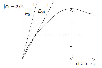
<Triaxial compression test result
graph>
The
use of K(bulk modulus) and G(shear modulus) may be debatable
use to the continuity issues associated with the ground,
but it can be expressed more simply and clearly than E
or v and is convenient to use. The following figure briefly
explains the mechanical significance of K and G.
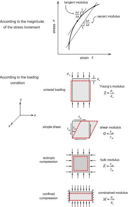
<Various types of Elasticity
modulus>
The
Elasticity modulus values gained from on-site tests can
be 1 of the many elasticity moduli discussed above and
can be modified appropriately for real situations.
Geo-material |
Elasticity
modulus (tonf/m2) |
Poisson’s ratio |
amphibolite |
9.4~12.1 ´106 |
0.28~0.30 |
anhydrite |
6.8
´106 |
0.30 |
siabase |
8.7~11.7 ´106 |
0.27~0.30 |
siorite |
7.5~10.8
´106 |
0.26~0.29 |
solomite |
11.0~12.1 ´106 |
0.30 |
sunite |
14.9~18.3
´106 |
0.26~0.28 |
deldspathic
gneiss |
8.3~11.9 ´106 |
0.15~0.20 |
gabbro |
8.9~11.7
´106 |
0.27~0.31 |
granite |
7.3~8.6 ´106 |
0.23~0.27 |
ice |
7.1
´106 |
0.36 |
limestone |
8.7~10.8 ´106 |
0.27~0.30 |
marble |
8.7~10.8
´106 |
0.27~0.30 |
mica
Schist |
7.9~10.1 ´106 |
0.15~0.20 |
obsidian |
6.5~8.0
´106 |
0.12~0.18 |
oligoclasite |
8.0~8.5 ´106 |
0.29 |
quartzite |
8.2~9.7
´106 |
0.12~0.15 |
rock
salt |
3.5 ´106 |
0.25 |
slate |
7.9~11.2
´106 |
0.15~0.20 |
aluminum |
5.5~7.6 ´106 |
0.34~0.36 |
steel |
20.0
´106 |
0.28~0.29 |
<The Elasticity modulus and
Poisson’s ratio for rock and other materials>
The
Elasticity modulus in the table above is for small, intact
rock samples tested in the lab. Hence, when considering
the site conditions, a reduced elasticity modulus needs
to be used considering the discontinuous surfaces within
large scale rocks. The figure below is a graph of actual
data showing the relationship between the RQD (Rock Quality
Designation) and the Elasticity modulus reduction ratio.
An RQD is the percentage of the sum of the lengths of
cracks that are over 10cm and exist on the 100cm situ
core against the total length. An RQD of 100% does not
mean the core is an intact rock. However, a higher RQD
means a higher quality rock and the RQD decreases with
more weathering.
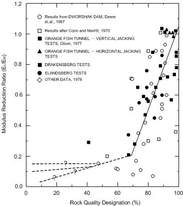
<RQD- Modulus reduction ratio
(EL/EM) relationship>
As
shown on the figure, an RQD of 70% already needs to decrease
the lab Elastic modulus by 20%.

[Increment
of Elastic modulus]
In
general, the strength properties of the soil change with
depth and confining pressure, even within a ground layer
composed of the same material. To take this characteristic
into account, increase or decrease in the Elastic modulus
can be simulated with reference to a reference height
(standard height). If the elastic increase according to
height is '0(zero)', the Elastic modulus has a constant
value and if it is not '0(zero)', the Elastic modulus
is calculated with reference to a standard height using
the following equation.
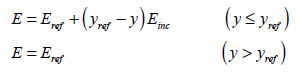
Here,
 : Input elastic
modulus value : Input elastic
modulus value
 : Incremental slope of
elastic modulus : Incremental slope of
elastic modulus
 : Depth of measurement : Depth of measurement
<Schematic diagram of Elastic
modulus increment>
The
 in the equation represent the integral
point positions of an element where the finite element
method calculation occurs. If the integral point position
is higher than in the equation represent the integral
point positions of an element where the finite element
method calculation occurs. If the integral point position
is higher than  ,
the elastic modulus value can be less than 0 in some places.
To avoid this, use the value
instead of further decreasing the ,
the elastic modulus value can be less than 0 in some places.
To avoid this, use the value
instead of further decreasing the  value.
[Poisson’s
ratio( )] )]
Poisson’s
ratio is a proportional constant from the stress-strain
relationship and displays the material volume change associated
with loading. As approaches
0.5, the material becomes an incompressible solid and
closer to 0 means the material is elastic, showing large
volume changes even at small loads. The initial stress
ratio due to self weight K0 = σh/ σv can be related to
the ratio in the uniaxial compression state by K0 = . If K0 is not used to define the initial
in-situ stress, the horizontal stress is calculated from
the vertical stress using the entered .
For geo-materials, the general Poisson range is within
0.3~0.4 and entering a value larger than 0.49 can cause
numerical errors. Hence, if K0 is larger than 1, for example
over-consolidated ground, the Poisson’s ratio cannot be
calculated and the value must be entered directly. . If K0 is not used to define the initial
in-situ stress, the horizontal stress is calculated from
the vertical stress using the entered .
For geo-materials, the general Poisson range is within
0.3~0.4 and entering a value larger than 0.49 can cause
numerical errors. Hence, if K0 is larger than 1, for example
over-consolidated ground, the Poisson’s ratio cannot be
calculated and the value must be entered directly.
Shear
modulus(G)
The
Shear modulus is automatically calculated from the Elastic
modulus and Poisson's ratio using the following equation
derived from Hooke's law. If the value is directly entered,
the Elastic modulus changes.
[Oedometer
Elastic modulus (Eoed)]
The
Oedometer modulus can be calculated from the Elastic modulus
and Poisson's ratio using the following equation.
[Initial
stress (K0)]
K0
is the Coefficient of earth pressure, which is defined
as the ratio of the initial vertical/horizontal stress
(K0 = σh/ σv). The anisotropic property can be set with
reference to the Global Coordinate System.
Firstly,
select yes/no on whether the Global Coordinate System
direction and anisotropic property match and set the lateral
pressure index in each axis or any direction depending
on the selected options.
When
the 2 properties do match, the lateral pressure index
is set in each axis direction but a value of ‘1’ in the
direction of gravity cannot be defined depending on the
work environment (2D/3D).
When
the 2 properties do not match, the lateral pressure index
direction is set by entering the angle with respect to
the reference axis. The reference axis exists to set the
lateral pressure index direction. For a 2D work environment,
the ’X-Y’ plane is fixed and only the ‘X’ axis can be
selected, with all initial shear stress at ‘0(zero)’.
For 3D, each axis apart from the gravitational direction
can be selected. For example, if the gravitational direction
is the ‘Z’ axis and the reference axis is set as the ‘X’
axis, the angle can be entered on the ‘X-Z’ plane will
be the maximum lateral pressure angle and all initial
shear stress in the XY and YZ direction will be '0(zero)'.
The
in-situ stress state, where the soil it not disturbed
by excavation or fill, can be expressed using the Coefficient
of earth pressure and self weight. In other words, realistic
results can be obtained from applying K0 after modeling
the in-situ ground for the 1st step of construction during
analysis. This is true for flat foundations but for inclined
foundations, it is recommended that another construction
process be added to converge the stress found using K0
for equilibrium.
[Thermal
Parameter]
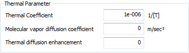
Thermal Coefficient - describes
how the size of an object changes with a change in temperature.
Specifically, it measures the fractional change in size
per degree change in temperature at a constant pressure.
Molecular
vapor diffusion coefficient - the
gas diffusion coefficient of a porous medium, which indicates
the change in gas density over time.
This
parameter will be used in a future release of FEA NX after
additional analysis enhancement.
Thermal diffusion enhancement
(factor) - controls
the degree of gas flow according to the temperature gradient
(unit less).
This
parameter will be used in a futurehttps://attendee.gotowebinar.com/register/5057000740216531467
release of FEA NX after additional analysis enhancement.
[Safety Result
(Mohr-Coulomb)]
§Cohesion,
Friction Angle and Allowable tensile strength (optional)
can be defined as the failure criteria.
§Stress
status of material for each construction stage can be
represented by Factor of Safety based on Mohr-Coulomb
failure criteria.
§The
ratio of generated stress to stress at failure for each
element will be calculated automatically.
§Users
can figure out stable, potential failure and plastic failure
area directly.
§Check
factor of safety for each element - (2D : Plain Strain Stresses
> SAFETY FACTOR , 3D : Solid Stresses > SAFETY FACTOR)
§In
case that Safety Factor is less than 1(or 1.2), it can
be identical with plastic failure region.
Porous: Seepage, Drained/Undrained
Parameter
The
input parameters for the permeability characteristics
and drained/undrained conditions of the foundation are
as follows.
Input
parameter |
Definition |
Unit |
Unit weight(saturated) |
Saturated
state unit weight |
kN/m3 |
Initial
void ratio(eo) |
Initial void
ratio |
- |
Unsaturated characteristic |
Unsaturated
characteristic function setting (negative pore
water pressure-water content-permeability ratio) |
- |
Drainage
parameter |
Drained/Undrained
condition |
- |
Permeability coefficient |
GCS
direction - Saturated permeability constant |
m/sec |
Void
ratio dependent permeability ratio (ck) |
Permeability
ratio dependent on void ratio |
- |
Specific
storage(Ss) |
Volume
ratio of water inflow/outflow |
1/m |
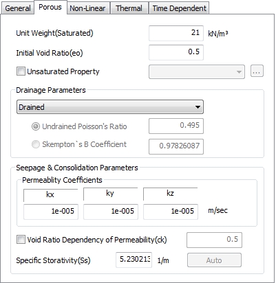
<Permeability parameter>
[Initial
void ratio (e0)]
The
initial void ratio of the foundation used in consolidation
analysis and stress-seepage coupled analysis. It is the
volume ratio between the voids and soil particles within
the soil and the value is less than 1 for most soils.
The value can be larger than 1 for clays or organic soils,
but the value depends greatly on the sampling method or
compaction. Generally, coarse grain sand has a value of
0.6~0.8 and high density sand with an even size distribution
has a value of 0.3. The void ratio can be even 2~3 for
fine grained soils.
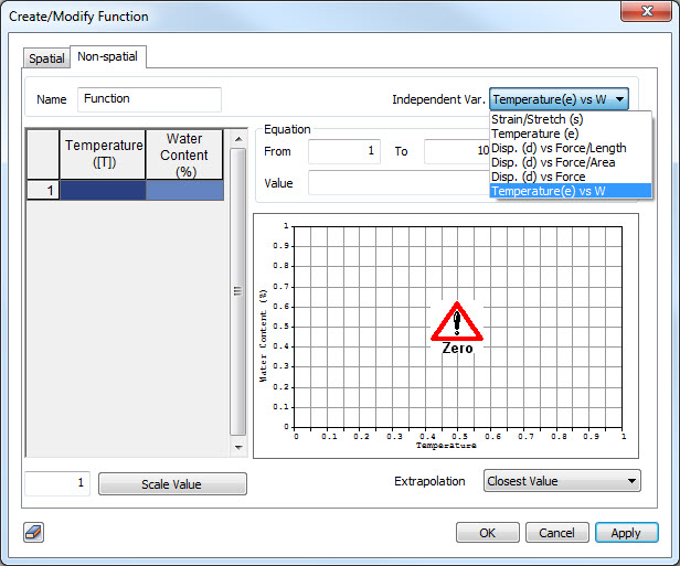
[Unsaturated
Property]
Set
to consider the unsaturated property of the foundation.
It is a required property for unsteady infiltration analysis
and is used to consider the partial degree of saturation
of the foundation for nonlinear (construction step)/consolidation
analysis etc. Because real foundations are unsaturated
and have a certain ratio of air, unsteady infiltration
analysis needs to consider unsaturated characters of the
soil for more realistic results. If the unsaturated properties
are not considered, it is assumed that the ground is saturated
and hence, the infiltration analysis with time cannot
be examined.
Unsaturated
property defines the change in permeability coefficient
and water content (Degree of saturation) in the unsaturated
region depending on the size of the negative pore water
pressure. There are 2 methods to define the unsaturated
property; directly defining (define individually) the
permeability function and water content function using
the pressure head (negative pore water pressure) or defining
the relationship between pressure head-volumetric water
content (degree of saturation)-permeability ratio (define
relationship). Refer to "Function>Unsaturated
characteristic function" for more information.
[Drainage
parameters]
The
pore water pressure in stress analysis can be divided
into normal state pore water pressure and abnormal state
pore water pressure - the excess pore water pressure generated
between soil particles due to external loading under undrained
conditions. An excess pore water pressure of nearly 0
is called the drainage condition and is generally used
for drainage analysis of sand, which has a large permeability.
However when simulating clay, which has a very small permeability
and water cannot be drained out during sudden loading,
undrained analysis is appropriate. The initial state,
where the excess pore water pressure has not yet dissipated,
is seen as the most unstable state and the pore water
pressure is determined by the volume change of the foundation
due to compressibility and permeability coefficient.
Undrained
Poisson’s ratio and Skempton(B) coefficient are parameters
used to calculate the bulk modulus of elasticity for water.
The undrained Poisson’s ratio has a standard value of
0.495 with a compressibility of nearly ‘0(zero)’ and the
Skempton coefficient expresses the saturation, with 1
meaning full saturation.
The
materials for the unsaturated analysis are as follows.
Please
refer to Ch.4 of the Analysis manual for more detailed
information.
Drained/Undrained
Materials |
Useable
Material models |
Drained |
All geo-materials |
Undrained
(Effective stiffness /Effective strength) |
Elastic,
Mohr-Coulomb, Drucker-Prager, Duncan-Chang,
Hoek-Brown,
Strain Softening, Modified Cam-clay, Jardine,
D-min, Modified Mohr-Coulomb, User-supplied, Transversely
Isotropic |
Undrained (Effective stiffness
/ Undrained strength) |
Mohr-Coulomb,
Drucker-Prager, Modified Mohr-Coulomb |
Undrained
(Undrained stiffness / Undrained strength) |
Elastic,
Mohr-Coulomb, Drucker-Prager, Modified Mohr-Coulomb |
[Permeability
coefficients (kx,ky,kz)]
The
permeability coefficient represents the permeability characteristics
(velocity) of the foundation and is used in infiltration
analysis and consolidation analysis. The permeability
coefficient for each direction can be defined on the GCS.
The input value is the saturated permeability coefficient
and becomes the standard for computing the permeability
ratio (Kunsat / Ksat) due to negative pore water pressure
when defining an unsaturated property function.
[Void
ratio dependency permeability (ck)]
The
permeability coefficient is a measurement of how much
the groundwater within a foundation moves in a unit time
and is dependent on the water content and the void ratio
change  . The larger water content, the
larger the flow channel and hence, the value is largest
when the foundation is saturated. The water content depends
on the pore water pressure and hence, the permeability
coefficient is also dependent on the pore water pressure.
The change in void ratio is considered in consolidation
analysis as well as stress-seepage coupled analysis and
is calculated from the initial void ratio. . The larger water content, the
larger the flow channel and hence, the value is largest
when the foundation is saturated. The water content depends
on the pore water pressure and hence, the permeability
coefficient is also dependent on the pore water pressure.
The change in void ratio is considered in consolidation
analysis as well as stress-seepage coupled analysis and
is calculated from the initial void ratio.
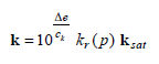
To
express the change in pore water pressure, FEA NX uses
the permeability ratio function  depended on saturated pore water pressure coefficient
 and pore water pressure change and the void
ratio dependent permeability ratio and pore water pressure change and the void
ratio dependent permeability ratio  dependent on void ratio change . The unsaturated permeability
coefficient depending on void ratio change is given by
the following equation.
dependent on void ratio change . The unsaturated permeability
coefficient depending on void ratio change is given by
the following equation.
[Specific
storativity(Ss)]
The
Specific storage is the water volume inflow or outflows
from the unit volume of the aquifer due to water level
rise or fall in a confined aquifer. A coefficient can
be directly entered or automatically calculated for compressible
fluids.
The
change in volumetric water content for pore water pressure
in infiltration and consolidation analysis can be expressed
by the porosity and degree of saturation.
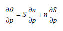
The
first clause is the slope of the volumetric water content
under saturated conditions that can be expressed using
the specific storage.
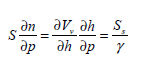
When
the material drainage property is set to undrained, the
specific storage is automatically calculated using the
undrained Poisson's ratio (vu) and the Effective elastic
modulus (E') and Poisson's ratio (v'), entered in the
general parameters.
Thermal
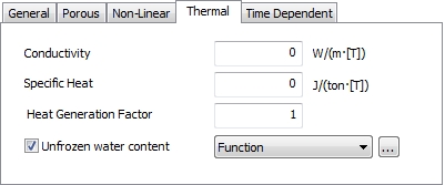
Conductivity: the ability to conduct thermal
energy.
Specific Heat: the amount of heat required to raise single
unit mass of a substance by single temperature unit. (required
for transient heat transfer problems)
Heat Generation Factor: the value of the heat load
multiplied by the exothermic coefficient used as the load
vector for heat transfer analysis is the total exothermic
load applied to the object.
Unfrozen water content: indicates floating water
content in soil / rock. It is given as a temperature-dependent
function as a unique characteristics of the ground.
Time Dependent
This
is to define Creep Formulation to simulate time-dependent
behavior of concrete structures. Following constitutive
models are available for concrete structures, Elastic,
Tresca, von Mises, Mohr-Coulomb, Drucker Prager, and Hoek
Brown.
Two
types of creep formulation are available to define Time-dependent
behavior of material, Age Dependent and Age Independent.
Refer to analysis reference Ch.4-Section5 in detail.
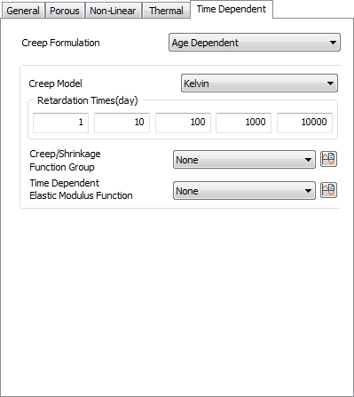 
[Age
Dependent]
The
stiffness of concrete changes with time, and the creep
and shrinkage may cause unexpected deformation. The creep
strain of concrete depends on the time of stress occurrence
even under the same applied load. FEANX supports aging-Kelvin
model and aging Viscous model excluding the spring from
Kelvin model.
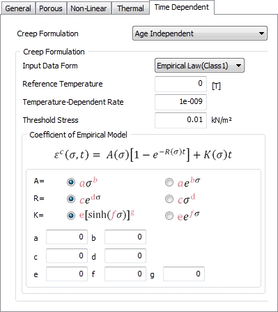
[Age
Independent]
FEANX
can take into account the primary and secondary creep.
The user can use two types of empirical law to define
the creep behavior.
|
