-
Reference Node : Select the reference node for the sectional direction of the 1D element. The element Z coordinate direction is set with reference to the selected node.
-
Reference Vector (GCS) : Set the Z coordinate direction of the selected element using the GCS direction or the input vector direction.
-
Beta Angle : Angles 0,90,180 can be chosen and the selected Beta angle rotates the element by that angle with reference to the X axis.
<Beta:0> <Beta:90> <Beta:180>
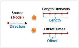
Extrude Direction
Select the element extrude direction with reference to the GCS or input the start and end points of the direction vector using the 2-point vector function. It is useful when extruding in an arbitrary direction.
Extrude Information
Set the total length and division of 1D element which will be created. The division spacing can be set as either uniform or nonuniform. Entering a negative value for length (Offset,Times) extrudes in the opposite direction to the axis or vector direction.
[Nonuniform]
Specify the offset length and number simultaneously. The length can be listed using a comma (,) or as number@length for continuously repeating extrude operations.
For example, entering 10@3 creates 10 elements with a length of 3 each and entering 2,3,4 creates 3 elements, each with a length of 2,3 and 4.
[Uniform]
Set the offset length or number, or input the total length and division spacing.
Advanced Option ( ) )
When checking the User defined mesh set, the generated elements are classified and registered in different mesh sets depending on the number of inputs in the [Offsets per Set] option. Entering a number registers the mesh sets in the specified uniform offset spacing and entering 2 or more numbers register the mesh sets in the specified uniform offset spacing and the rest are registered separately on the mesh set. When entering 2 or more numbers, the sum of input numbers should not be more than the total number of offsets.
|