Setting
the vector properties Setting
the vector properties
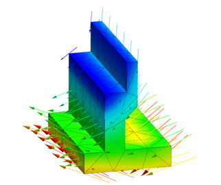
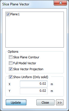
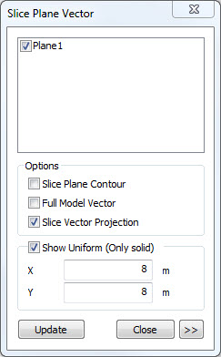
Use
vectors to display the analysis results on the
work screen. This option can be used to set how
the vectors will be displayed.
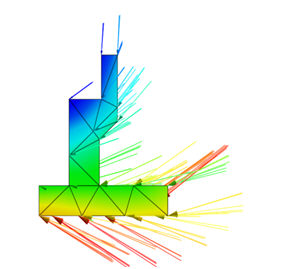
Vector
> Scale Factor
Plot
the scaled vector results.
 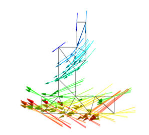 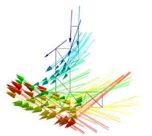
<Scale
value = 2 > <cale
value = 5> <Scale
value = 10>
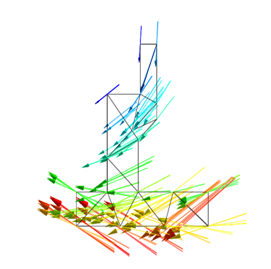
Vector
> Start Position
Determine
the arrow position.
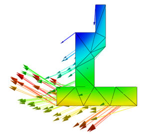 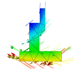 
<Start
position = Start> <Start
position = Center> <Start
position = End>
Vector
> Plot All Components
When
the principal stress vector of an element is output,
both the maximum and minimum principal stresses
are output if True.
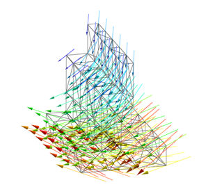
Vector
> Only Free Face
Only
plot the arrows for nodes on the free face.
 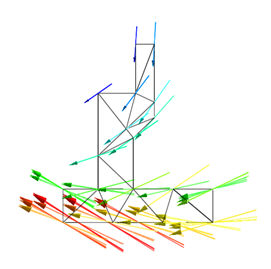
<Only
free face Unchecked(False)> <Only
free face checked(True)>
Head
> Type
Determine
the vector arrowhead direction. (One direction/
Two direction/ No direction)
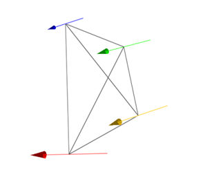 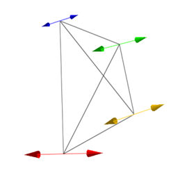 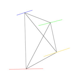
<One
direction> <Both
direction> <No
direction>
Head
> Constant Size
Set
all vector arrowheads to an equal size. (True/False)
Head
> Scale Factor
Plot
the scaled vector arrowhead. (Scale Value)
Body
> Constant Size
Set
all vector arrow body lengths to an equal size.
(True/False)
Body
> Scale Factor
Plot
the scaled vector arrow body length. (Scale Value)
Body
> Line Width
Plot
the scaled vector arrow body thickness. (Scale
Value)
Color
> User Color
Plot
the vector arrow using the user defined positive
and negative colors. (True/False)
Color
> Plus Value Color
When
setting the user color, determine the positive
value vector arrow color.
Color
> Minus Value Color
When
setting the user color, determine the negative
value vector arrow color. |