▒
Overview
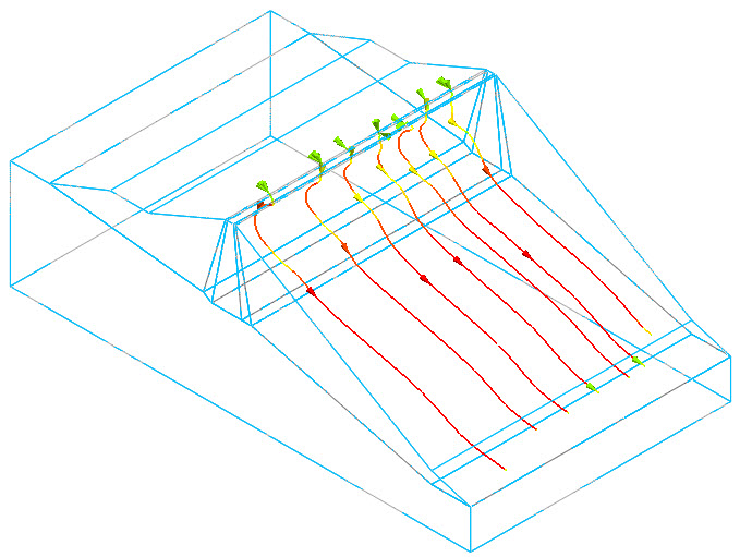
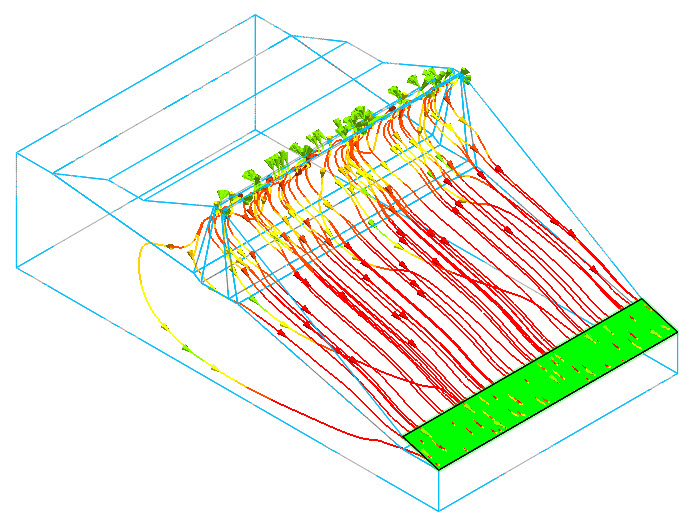
 Identify the
flow path and flow quantity values obtained from the Seepage
analysis results. Identify the
flow path and flow quantity values obtained from the Seepage
analysis results.
|
▒
Methodology
Flow
Path
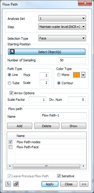
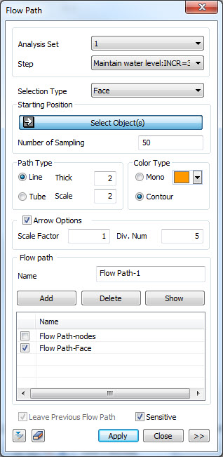
<Flow path>
Specify the analyzed analysis
case and step, and then input the coordinates of the
flow path display position (an arbitrary point on
the flow path). Snap option can be used to input the
coordinate values. Under [Selection Type]
option selection method can be chosen: Node or Face.
Multi-path selections (definitions) can be created
and stored under Flow Path section.
Press Show button to display defined flow paths. The flow path can be displayed
as a line or pipe. For a line, the line thickness
and for a pipe, Scale can be used to adjust the size. The flow path color can
be selected between Single color and Contour. The arrow grid option is
an indicator that represents the flow direction of
the flow path. The scale value and number can be used
to adjust the arrow size and number of arrows. If the [Leave Previous
Flow Path] option is checked, a flow path is displayed
for every clicked position on the screen. If this
option is unchecked, a flow path is displayed only
on the last clicked position. If the [Sensitive] option
is checked, the flow net is displayed on the screen
immediately. If this option is unchecked, the [Apply]
button needs to be pressed in order to display the
flow net.
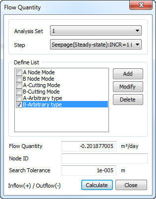
Flow Quantity
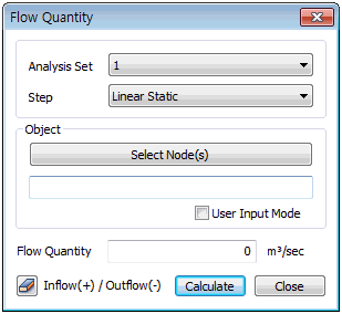
Specify the analyzed analysis
case and step, and then select the nodes where the
flow quantity will be calculated. The nodes can be selected
and specified on the screen, or [User Input Mode]
can be checked to input the node ID if the node number
is known. Press the Calculate button
to automatically calculate the flow quantity at the
nodes, and the calculated flow quantity value is expressed
on the dialog.
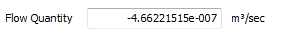
The flow quantity at each
node is made up of the flow rate value sum, and (+)
indicates inflow while (-) indicates outflow. The
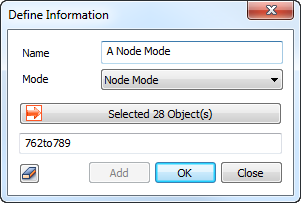
node selection method (Node Mode), line/plane
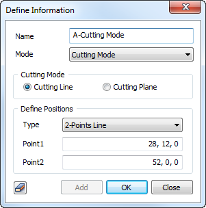
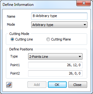
definition method (Cutting Mode) and Arbitrary Type
are supported. Nodes/Cutting
Mode - returns the flow rate by summing the flow rates
calculated at the nodes by direct selection or input
of the nodal points where the outflow or inflow occurs. Arbitrary
type - calculates the flow of elements through any
line or plane
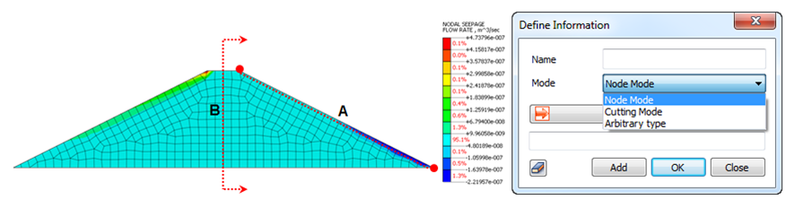 There
are ‘Cutting Line’ and ‘Cutting Plane‘ option in the
‘Cutting Mode’. The ‘Cutting Line’ option calculates
flow quantity from nodes within the 'Search Tolerance'
by defining ‘2-Points Line’ directly or selecting
‘Edge’. The ‘Cutting Plane‘ option calculates flow
quantity from nodes within the 'Search Tolerance'
by defining ‘3-Points Plane’ directly or selecting
‘Plane’. The ‘3-Points Plane’ type calculates flow
quantity from the infinite plane consisting of three
points or the plane only consisting of them with the
'Limited Plane' option. Once
the information for calculating flow quantity is created
in the ‘Define Information’ dialogue box, it will
be registered in the ‘Define List’. Flow quantity
can be calculated by duplicate selecting a number
of information registered in the ‘Define List’ and
they can be modified or deleted as well. The node
information included in the checked ‘Define List’
is displayed in the ‘Node ID’ and duplicated same
nodes of a number of information will be treated as
one.
|

|
|