General
Input
the number of tunnels and tunnel shapes, and set the excavation
method.
First,
decide whether to model the full tunnel face or the half(right)
of the full tunnel face. Be aware that the specified construction
stages and result data etc. cannot be used if the model,
created using the Tunnel Modeling Wizard, is modified
later.
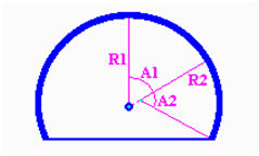
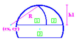
[Shape]
Determine
the tunnel shape. Circular, 3 Center circle, 5 Center
circle shapes are supported. The dimensions specify the
tunnel changes, depending on the specified tunnel shape.
Set the input guide to display the relationship between
the tunnel shape and input values on the Tunnel Wizard
dialog box. The guide can be used as a reference when
entering the variables. The input values for the tunnel
shape are the same as for Geometry > Point&Curve
> Tunnel (Wire).
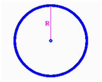 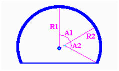 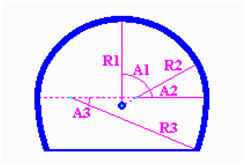
<Circular> <3
Center circle> <5
Center circle>
[Property]
Input
the ground material around the tunnel. If the tunnel model
is created using the Tunnel Wizard, a basic rectangular
ground shape can be created around the tunnel and the
upper stratum and index shape can be added to the model
optionally. A basic model is the rectangular ground shape
on the periphery of the tunnel. The basic shape can be
composed of a homogeneous material. The material and properties
are the same as the specified Material property in Property/Coordinate
and System/Function.
[Excavation
Method]
Determine
the excavation method for the tunnel section. FEA NX supports
the section shapes for [Full Face Cut], [Bench cut 1],
[Bench cut 2], [Ring cut 1], [Ring cut 2] and [3D cut]
  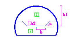
<Full face cut> <Bench
cut 1> <Bench
cut 2>
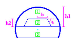 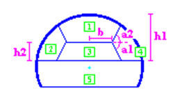 
<Ring cut 1> <Ring
cut 2> <CD
cut>

Shotcrete & Rock Bolts
The
Shotcrete & Rock Bolts tab determines the generation
of shotcrete and rock bolts, type and material, arrangement,
shape, etc.
The
generation of shotcrete, soft shotcrete and rock bolts
can be set using the checkbox. Shotcrete and soft shotcrete
are specified as plate elements and rock bolts are specified
as embedded truss elements.
The
material and properties are the same as the specified
Material Property in Property/Coordinate System/Function.
The properties of shotcrete & rock bolts must be specified
as a structural property.
[Add
Shotcrete to the Intermediate Wall]
If
the 3D cut tunnel excavation method is activated, the
installation of shotcrete on the intermediate wall can
be decided.
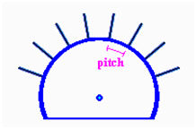
[Rock
Bolts]
Input
the number, division length and spacing between rock bolts
(Tangential pitch).
This option determines whether
to place the rock bolts in an intersecting array for each
construction stage. Setting +1 creates the set number
of rock bolts in the first construction stage, an extra
rock bolt is added in the second stage, and the number
returns back to the set number in the third stage. Setting
-1 creates the set number of rock bolts in the first construction
stage, a rock bolt is removed in the second stage, and
the number returns back to the set number in the third
stage.
The
[Add Rock Bolt to the Intermediate Wall] option is activated
when the tunnel excavation method is set as 3D cut, and
determines whether to install a rock bolt on the center
wall.
<Rock
bolt> <Add
rock bolt to center wall>
[Input
Guide] or [Drawing] can be used to check the drawn section
shape in real time.
Excavation
Determine
the tunnel excavation for each construction stage.
Select
the excavation type, whether to excavate in one direction
or in both directions. For both directions, the program
creates the construction stages until the tunnel is perforated.
After this point, the user needs to create the construction
stages directly.
When
modeling 2 tunnels, specify the tunnel to be excavated
first.
[1st
Excavation Tunnel]
Input
the stage spacing for shotcrete and rock bolts after excavation.
For example, if 1 is inputted, the shotcrete or rock bolts
are created in the subsequent stage after excavation.
When creating soft shotcrete, the soft shotcrete is created
in the specified stage and then stiffens in the next stage.
[2nd
Excavation Tunnel]
Input
the excavation stage for the second tunnel in the case
of two tunnel construction. For example, if 2 is inputted,
one tunnel is excavated and the next tunnel is excavated
2 stages later. The shotcrete and rock bolt creation point
is determined by the specified value in Define Stages
after the 1st Excavation.
[Advancing
Length]
Specify
the excavation length for each construction stage. Entering
advancing length automatically calculates and displays
the total tunnel length. The excavation length for each
construction stage is input using commas or spaces. Repeating
lengths can be input using number@length. For example,
if the excavation is done for lengths of 2,2,2,2,3,4,
input ‘2,2,2,2,3,4’ or 4@2,3,4.
Divisions
are the number of created elements in the excavation direction
for each excavation stage. If loading is needed, click
the  button to input the load
distribution factor for each stage. button to input the load
distribution factor for each stage.
[Rock
Bolt Location]
Input
the rock bolt creation location for each construction
stage. Rock bolts can be automatically created at the
center of the excavation length of each stage and the
user can directly input the pitch and angle to adjust
the creation location.
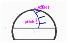
[Pitches]
expresses the rock bolt creation location using the start
portion of the tunnel and the rock bolt creation location
of the previous stage.
[Angle]
is the angle between the tunnel length direction and the
rock bolt.
Mesh
Input
the mesh shape, strata and ground surface shape.
For
the tunnel location, the model depth, the distance from
tunnel floor to the lower boundary of the model, the distance
from the tunnel to the left/right boundaries of the model,
and the distance between tunnels for 2 tunnel construction
can be input.
Each
boundary distance is input as a multiple of the tunnel
floor width.
[Ground
Modeling]
Model
the upper stratum. The upper stratum can be modeled using
the [Actual] or [Load] methods.
The
[Actual] method creates real meshes to conduct modeling.
The [Load] method does not model the ground surface shape
directly, but processes it as a pressure load.
The
reference height is the [Base Elevation] on which the
input values from the created stratum or terrain will
be added.
[Strata]
The
stratum exists above the upper part of the tunnel, and
multiple strata can be created using the [New] button.
The material and properties are the same as the specified
material property in Property/Coordinate System/Function.
Input the stratum shape following
the model width direction. Input the width coordinates
in the x direction. The origin is located at the bottom
left corner of the tunnel as viewed from the front.
Input the height value at
each x coordinate position. Input the x coordinate and
value to draw the input shape on the right.
Input the stratum shape following
the tunnel direction. Input the tunnel length direction
coordinates in the z direction. The origin is located
at the bottom left corner of the tunnel as viewed from
the front.
Input the height value at
each z coordinate position. The height value is the change
in height respective to the previous value.
[Terrain]
Model
the terrain. The terrain is generated using virtual grids
identical to the grid face. The height is input at the
grid intersections. The terrain height on a text file
can be imported or the height can be input directly.
The
material and properties are the same as the specified
material property in Property/Coordinate System/Function.
[Mesh
Size]
Input
the size of the mesh created in the tunnel. For the tunnel
(Interval), the user can input the mesh size directly.
The mesh boundary is input as a multiple of the created
mesh size. Using the automatic setting sets the boundary
element size automatically.
Open
Open
a saved Tunnel Wizard file (*.wzd).
Save as
Save
the entered values in current Tunnel Wizard as a Tunnel
Wizard file (*.wzd).
Save Default Data
Set
the current input values as the default values of the
Tunnel Wizard.
Open Default Data
Delete
all current input values and reset to the default values
of the Tunnel Wizard. |
