Change property
Change
the property assigned to a 2D element during its
creation. Select the 2D element to modify and
specify the property to change.
Change
element order
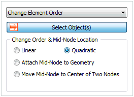
Add or delete nodes between
a 2D element to change it into a higher order
or lower order element. Changing the position
of the middle node to the start or end point for
high order element can create an arbitrary middle
node on the geometry shape.
Change
coordinate system
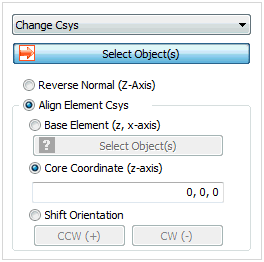
For a 2D structural element,
the print coordinate system (material coordinate
system) can be defined separately. Here, if the
print coordinate system (material coordinate system)
is set as the element coordinate system, it is
important to check the coordinate system of the
structural element to make sure it is in 1 direction.
Switch the element z axis direction or unify the
normal directions of the selected elements to
the normal direction of the reference element.
When using centered coordinates, use the direction
vector from the reference point to each element
to modify the normal direction of each element.

Add
Thickness
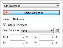
The thickness
of a 2D element is defined in the section properties,
but an additional thickness can be specified for
selected elements. Select the 2D element and change
the thickness by specifying the thickness for
each element node.
Add
Offset
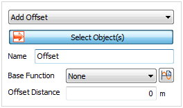
Define
the offset distance by considering the sectional
properties (shape) of the structural element.
The offset is the eccentric distance between the
positions of the geometry shape (surface), needed
to create a structural element, and the reference
axis, where the loading is applied and the results
are calculated. The distance can be specified
by a function on the GCS and the direction moves
to the normal direction (+,-) of the 2D element.
When applying the function, the input offset distance
becomes the scale factor that is multiplied to
the function for calculation.
Add
Material Orientation
Apart
from the material coordinate system specified
on the 2D element property, a separate material
coordinate system (print coordinate system) can
be additionally set for selected elements. The
coordinate system can be defined as follows.
Coordinate System:
Specify the material x direction in the X,Y,Z
direction of the GCS. Both the Global rectangular
coordinate system and Global cylindrical coordinate
system can be used. Angle:
Specify the material x direction by setting
the normal direction of the element as the
revolution axis and rotating the coordinate
system by the specified angle. Reference
Vector: Input or use the selected space vector
direction to specify the material X direction. Coordinate
system and Angle: Specify the material X direction
as the rotated direction of the reference
coordinate axis on the selected coordinate
plane.
Add
End Release (Shell)
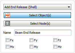
Specify
the selected node boundary conditions for a 2D
element. The axial direction and rotation conditions
can be released for each element. |


