Buckling Analysis Control
Enter the load cases and related data for the buckling analysis of a structure.
midas Civil follows the procedure noted below for buckling analysis.
1. A buckling analysis process requires static analysis results to formulate the initial geometric stiffness matrix. Accordingly, enter the load cases to be applicable for the buckling analysis following the procedure for static analysis.
2. Invoke the dialog box of the Analysis > Analysis Control > Buckling Analysis Control menu and enter the required number of modes and data necessary for convergence and assign the load combination to be applied to the buckling analysis.
3. Select the Analysis > Perform Analysis menu or click ![]() Perform Analysis to carry out the analysis.
Perform Analysis to carry out the analysis.
4. Once the analysis is successfully completed, use either the Results > Buckling Mode Shapes function or the Results > Result Tables > Bucking Mode Shape function to review the buckling mode shapes and critical load factors for each mode shape.
5. To calculate buckling loads, enter the self-weight (Constant) and additional loads (Variable) and then perform the analysis. The Eigenvalue resulting from the analysis is the critical load factor. Accordingly, the buckling load = critical load factor× additional load (Variable) + self-weight (Constant).
From the Main Menu select Analysis > Analysis Control > Buckling.
 Buckling Modes
Number of Modes: Enter the number of buckling modes.
Positive Value Only: Produce the eigenvalue results only for the loading direction.
Note
Once buckling analysis is performed, buckling modes are computed for both the loading direction and the opposite direction. However, for static loads whose loading direction is fixed, it is not necessary to compute the buckling mode shape and factor for the opposite direction.
|
Buckling Analysis may not be carried out in conjunction with P-Delta Analysis or Eigenvalue Analysis. Buckling Analysis is limited to truss element, beam element (including tapered beam element) and plate element.
To delete all the entered data, click ![]() .
.
![]() Revision of Civil 2015 (v1.1)
Revision of Civil 2015 (v1.1)
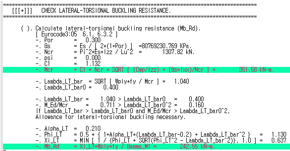
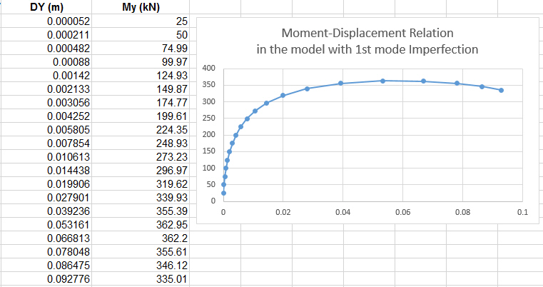
Q1. Can midas Civil consider second-order incorporating lateral torsional buckling directly?

