Construction Stage Analysis Control
A civil structure such as a suspension bridge, cable stayed bridge or PSC (prestressed or post-tensioned concrete) bridge requires separate and yet inter-related analyses for the completed structure and interim structures during the construction. Each temporary structure at a particular stage of construction affects the subsequent stages. Also, it is not uncommon to install and dismantle temporary supports and cables during construction. The structure constantly changes or evolves as the construction progresses with varying material properties such as modulus of elasticity and compressive strength due to different maturities among contiguous members. The structural behaviors such as deflections and stress re-distribution continue to change during and after the construction due to varying time dependent properties such as concrete creep, shrinkage, modulus of elasticity (aging) and tendon relaxation. Since the structural configuration continuously changes with different loading and support conditions, and each construction stage affects the subsequent stages, the design of certain structural components may be governed during the construction. Accordingly, the time dependent construction stage analysis is required to examine each stage of the construction, and without such analysis the analysis for the final stage alone will not be reliable.
midas Civil considers the following items for a Construction Stage analysis
The procedure for construction stage analysis is shown below.
|
Procedure |
Menu |
|
1. Define material properties |
Model>Properties>Material... |
|
2. Define section properties |
Model>Properties>Section... |
|
3. Define groups -Structure groups -Boundary groups -Load groups |
Model>Group> ① Define Structure Group... ② Define Boundary Group... ③ Define Load Group... |
|
4. Create elements and assign them to the structure groups |
Model>Elements>Create Elements... |
|
5. Define boundary conditions and assign them to the boundary groups |
Model>Boundaries>... |
|
6. Enter loads and assign them to the load groups |
Load>... |
|
7. Define time dependent material (concrete) -Creep, Shrinkage, Compressive strength |
Model>Properties> ① Time Dependent Material (Creep/Shrinkage) ... ② Time Dependent Material (Comp. Strength) ... |
|
8. Assign the time history material data to the material properties (concrete) |
Model>Properties>Time Dependent Material Link... |
|
9. Apply the geometric shape dimension of frame elements to calculate creep/shrinkage |
Model>Properties>Change Element Dependent Material Property... |
|
10. Construction stage - Specify the duration of the construction stage - Activate or deactivate relevant element (structure) groups - Activate or deactivate relevant boundary groups - Activate or deactivate relevant load groups |
Load>Construction Stage Analysis Data>Define Construction Stage... |
|
11. Construction stage analysis option - Considering time dependent effect - Load Cases to be distinguished from Dead Load |
Analysis>Construction Stage Analysis Control |
|
12. Perform analysis |
Analysis>Perform Analysis... |
|
13. Check analysis results for each construction stage |
Results> |
|
14. Check column shortening |
Results>Column Shortening Graph for C.S. |
From the Main Menu select Analysis > Analysis Control > Construction Stage.
![]() Final Stage
Final Stage
Assign a stage to be considered as the Final Stage of the construction stage analysis.
Last Stage
Assign the last stage as the true last stage.
Other Stage
Assign a stage within the overall construction stages as the final stage.
![]() Restart Construction Stage Analysis
Restart Construction Stage Analysis
Restart the construction stage analysis from the stage specified by the user. Restarting the analysis from the modified stage will save time.
![]() : Select the stages to be used for Restart.
: Select the stages to be used for Restart.
-
In order to use Restart function, analysis results corresponding to each construction stage should be stored in DB. It would be effective, in terms of time and storage, to select only the stages that are necessary for Restart and to save intermediate files just in case the program stops.
-
Restart function is performed using the results obtained from the previously performed analysis. When there are some changes that can affect the results of the stages after which Restart function is applied, the analysis results may not be consistent. The following are the cases:
-
-
When some changes are made to the structural system of the stages after which Restart function is to be applied
-
When some changes are made to the boundary conditions and loadings of the stages after which Restart function is to be applied
-
When some changes are made to the material or sectional properties that are used throughout the entire stages
-
The consistency of the analysis results using Restart function is dependant upon the input data. Therefore, as far as the final result is concerned, it is recommended to perform analysis from the start to end stages rather than using the Restart function.
-
![]() Analysis Option
Analysis Option
Analysis Type
Select linear analysis or geometric nonlinear analysis.
Linear Analysis
Independent Stage
Linear analysis is carried out independently in models of each construction stage.
Accumulated Stage
Linear analysis is carried out with accumulated effects of the models of each construction stage.
Include P-Delta Effect Only
Check to reflect the geometrical stiffness due to axial force in the analysis.
Nonlinear Analysis
Nonlinear analysis is used to reflect the change of geometric shapes of the geometric nonlinear analysis in the construction stage analysis. Geometric nonlinear analysis for Independent Stage Model cannot account for time dependent effects simultaneously. However, with Accumulative Geometric Nonlinear Stage Model, the program not only accounts for time dependent effects but also has an option to select the Pretension Type of cables and calculates tangential displacements while taking Lack of Fit Forces into account.
Independent Stage
Geometric nonlinear analysis is carried out independently in models of each construction stage. This option is used for the backward analysis of a suspension bridge considering large displacement.
Accumulated Stage
Geometric nonlinear analysis is carried out with accumulated effects of the models of each construction stage. This option is used for the forward analysis of a cable stayed bridge considering large displacement.
Include Equilibrium Element Nodal Forces
This option is associated with the Load > Initial Forces > Large Displacement, which is checked on to generate external nodal forces to equilibrate the initial member forces. This option is used for the geometric nonlinear backward construction stage analysis of a suspension bridge.
Include Time Dependent Effect
Check to reflect the time dependent material properties such as the change of modulus of elasticity, creep and shrinkage in the construction stage analysis.
Note 1
Geometric Nonlinear Accumulated Stage Analysis
-
Geometric nonlinear analysis should be performed based on Real Displacement. Therefore, "Initial Tangent Displacement for Erected Structures" option should be checked on. Even if the user does not check this option and clicks OK, the program internally will apply this option.
-
For the geometric nonlinear analysis in cable stayed bridge, elements except for cable elements cannot be installed, loads other than cable pretension cannot be active and boundary conditions cannot be active in the stage at which cable elements are installed.
-
In the case when supports (links, springs, etc.) become activated during construction stage, the supports should be activated earlier than the elements connected to the elements. If the elements are activated earlier than the supports, the supports should be activated with the "Original" option selected at the next stage. If the elements and supports are activated at the same time, displacements occurring at the elements are transferred to the boundary conditions and accordingly, incorrect results may be obtained.
Note 2
Analysis result is produced at both I and J ends only in geometry nonlinear analysis.
![]() Time Dependent Effect
Time Dependent Effect
If "Include Time Dependent Effect" is checked on in the Analysis Option,Click the ![]() to get the dialog box to input the time dependent information.Define the material properties related to creep and shrinkage in Time Dependent Material(Creep/Shrinkage)
to get the dialog box to input the time dependent information.Define the material properties related to creep and shrinkage in Time Dependent Material(Creep/Shrinkage)
Creep & Shrinkage
Type
Select one of the options for considering creep and/or shrinkage.
Creep
Convergence for Creep Iteration
Specify the convergence requirement for ending the repetitive process in the analysis reflecting creep.
Number of Iterations: Maximum number of repetitions
Tolerance: for convergence
Only User's Creep Coefficient
Perform the construction stage analysis only using the creep coefficients entered by the user. Creep coefficients are entered by elements in Creep Coefficient for Construction Stage.
Internal Time Steps for Creep
Specify a number, which is used to divide a construction stage to create internal steps for considering creep.
Note
Internal Steps are applied in the process of analysis, and the corresponding analysis results are not produced.
Auto Time Step Generation for Large Time Gap
Specify a number, which is used to divide a construction stage to create internal steps when the duration of the construction stage is too long.
Note
Internal Steps are applied in the process of analysis, and the corresponding analysis results are not produced.
Tendon Tension Loss Effect (Creep & Shrinkage)
Check on to reflect the effect of prestressing tension loss of tendons due to creep and shrinkage. Define the tendon properties of the prestressing loss in "Tendon Property".
Consider Re-Bar Confinement Effect
Check on to reflect the effect of rebar confinement for creep and shrinkage. Rebar data can be defined in "Reinforcement of PSC Section".
Variation of Comp. Strength
Check on to reflect the change of modulus of elasticity related to the change of compressive strength of concrete. The maturity variant property is defined in "Time Dependent Material(Comp. Strength)".
Tendon Tension Loss Effect (Elastic Shortening)
Check on to reflect the prestressing tension loss of tendons due to the elastic deformations of concrete.
Note
Prestressing tension loss in tendons due to elastic deformations is caused by other loadings such as live loads, creep, shrinkage, prestressing other tendons, etc after the prestressing force is applied. Note that it is not the same as the elastic shortening loss, which is one of the instantaneous losses.
![]() Non-Linear Analysis
Non-Linear Analysis
Click on the ![]() after checking the "Nonlinear Analysis control" and enter the following information in the dialog box below:
after checking the "Nonlinear Analysis control" and enter the following information in the dialog box below:
Number of Load Steps: Input the number of load steps for the non linear analysis.
Maximum Number of Iterations/Load Step: Maximum number of iterations of analysis per Load Step.
Convergence Criteria: Specify the basis on which to assess the convergence. Enter the norm values for Energy (Member force x displacement), displacement and member forces.
Note
The selection of the convergence criteria for repeating or ending the analysis must be based on the condition to reflect the effects of various degrees of freedom. For example, in the case of Displacement Norm, if the displacement resulting from the corresponding analysis step is {D1}, and the total displacement accumulated from each step is {D2}, the Norm is expressed as ![]() . If this value is smaller than the specified value, a convergence is considered to have occurred and the program stops the iterative analysis.
. If this value is smaller than the specified value, a convergence is considered to have occurred and the program stops the iterative analysis.
![]() P-Delta Analysis
P-Delta Analysis
Click on ![]() after checking on "Include P-Delta Effect Only" under the Analysis Option and enter the following data in the dialog box
after checking on "Include P-Delta Effect Only" under the Analysis Option and enter the following data in the dialog box
Number of Iterations: Maximum number of iterations of analysis
Convergence Tolerance: Tolerance for convergence
![]() Load Cases to be distinguished from Dead Load for CS Output
Load Cases to be distinguished from Dead Load for CS Output
Dead Load is generally the most significant component of all the loads applied to construction stage analysis. The results of all the load cases except for Creep, Shrinkage and Relaxation of Tendons are lumped into CS: Dead Load. Here we can select certain load cases to be distinguished from the Dead Load and produce the results under CS: Erection Load.
Add : Add an erection load case to be distinguished from Dead Load for C.S. Output.
Modify : Modify an existing erection load case selected from the list.
Delete: Delete the selected erection load cases from the list.
Load Case Name: Select the Load cases to be distinguished from Dead Load
Load Type for CS: Specify a load type classified into CS:Erection, which is differently categorized from CS:Dead. This is helpful in distinguishing the pre-composite dead load from the post-composite long term loads for the Steel Composite design as per AASHTO code. This is effective when the Auto Generation function is used for generating the load combinations.
Assignment Load Cases: Select the load cases from the load case list to be classified as erection loads.
Note
Multiple erection load cases can be defined.
 Cable-Pretension Force Control
Define the method of applying the pretension forces in cable elements.
Internal force: Apply the pretension forces as internal forces (which change after redistribution within the structure in the current construction stage).
External force: Apply the pretension forces as external forces forces (which remain unchanged in the current construction stage).
Note
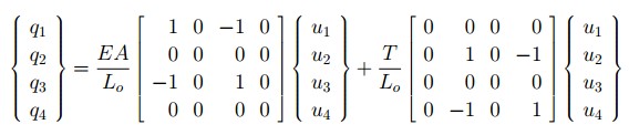
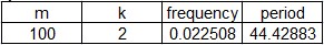
Pretension load is based on the concept of imposing deformation on the truss element in a structure. The method of introducing such deformation is tantamount to installing a truss element shorter than the length of the original element. The length is shorter by the magnitude of deformation. Once a shorter length element is installed in the overall structure, it has an effect of pulling the structure from the nodes to which the element is attached. The deformation is determined by the force and the stiffness of the truss element. (L = (P*L)/(E*A))
Pretension load of Internal Type is applied as deformation in the member equivalent to the pretension load, and the overall structure is analyzed. The resulting member force depends on the stiffness of the end nodes to which the member is attached. Upon applying the deformation to the truss member, large nodal displacements of the end nodes would imply a small member force, and vice versa. If the end nodes are fixed, the resulting member force will be equal to the specified pretension load. When other loads are acting on the member in the same load case, the principle of superposition applies.
Pretension load of External Type is applied to a member when we wish to impose the member to be subjected to the specified pretension load, while the overall structure is analyzed. This leads to the applied pretension load becoming equal to the resulting member force. When a pretension load is inducted into a cable in a particular construction stage, we are controlling the tension in the cable as opposed to controlling its deformation to a uniform magnitude. The External Type load has been implemented so that a specific tension force can be maintained in a particular cable in a particular construction stage. If other loads are applied to the member in the same load case, the resulting member force will remain constant as the pretension load.
The External Type load can be used only in the current construction stage. The options, Add and Replace, are provided to handle when pretension load is input more than once. If Add is checked on, any subsequent pretension load applied to a member will be added to the pre-existing force in the member. If Replace is selected, a pretension load applied to a member is maintained considering the pre-existing member force. The program automatically computes the additional tension force to make the tension force in the member equal to the specified pretension value.
Since a pretension is a loading, it is independent of the stiffness of the structure. Even in the case of the cable element, whose stiffness changes with tension forces, pretension is treated as a regular load.
Add: Add external pretension forces to the pre-existing tension forces of cable elements.
Replace: Replace the pre-existing tension forces of cable elements with applied external pretension forces.
Note
If the initial pretension forces are applied as internal forces, the forces in the cable elements become reduced due to the deformation of the support structure based on its stiffness. If the initial pretension forces are applied as external forces, the forces are treated as external loads to the support structure at the construction stage of pretensioning; hence the forces in the cable elements remain unchanged as the initial pretension forces at the corresponding construction stage.
![]() Initial Force Control
Initial Force Control
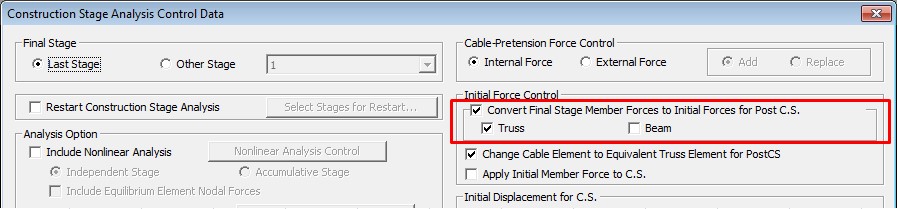
Convert final stage member forces to Initial forces for PostCS
The member (axial) forces of the last step of the last construction stage in a construction stage analysis are converted into Initial Force for Geometric Stiffness to reflect the forces into the geometric stiffness of the structure at the post construction (Post CS) stage. Converted member forces of the last construction stage are shown in the main menu, Load > Initial Forces > Small Displacement > Initial Element Forces(CS) table and reflected in the analysis at Post CS. This functionality will become quite useful when a forward analysis is carried out for a suspension or cable stayed bridge and the cable tensions at the last step are used as Initial Force for Geometric Stiffness.
If both Initial Element Forces table and Initial Element Forces(CS) table are entered, Initial Element Forces table directly entered by the user will be applied first in priority. However, if Apply Initial Member Force to C.S. is checked on, (Initial Element Forces(CS)) at the last step of the last construction stage will be applied to the Post CS stage.
Truss: Applicable for Truss and Cable elements (When Include Nonlinear Analysis option is activated)
Beam: Applicable for Beam elements
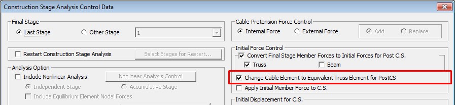
Change Cable Element to Equivalent Truss Element for PostCS
Load cases considered at post construction stage (Post CS or Completed stage) in cable stayed bridge or suspension bridge analysis include linear static load cases (ST), moving load cases (MV), settlement load cases (SM) and response spectrum load cases (RS). In moving load analysis, cable elements are automatically considered as truss elements. On the other hand, linear static analysis reflects true stiffness of cable elements. As such, it is not correct to linearly combine the analysis results obtained by different stiffnesses for the same elements. This function applies the same cable element stiffness to all the load cases acting in Post CS.
Check on: Equivalent cable element stiffness is calculated using the tensions in the cable elements at the last construction stage. The equivalent stiffness is then used to analyze all the load cases in Post CS. Change in stiffness due to changes in tensions in the cable elements is not recalculated for linear load combination. By checking this function, the same stiffness can be applied to various load cases at Post CS.
Check off: Different stiffnesses are applied to each load case as below.
|
Load Case |
Stiffness |
|
|
Linear Static Load cases |
Linear analysis |
Equivalent Truss Element |
|
Nonlinear analysis |
Elastic Catenary Cable Element |
|
|
Moving Load Case Settlement Load Case Response Spectrum Load Case |
Truss Element |
|
Apply Initial Member Force to C.S. :
Apply initial forces entered in the Initial Element Forces table to member forces for construction stages. The initial forces are applied to a specific construction stage at which the corresponding elements are first activated. This function is useful when we perform construction stage analysis from a specific construction stage by considering the member forces of the preceding construction stage as initial forces. Initial forces entered during construction stages will not be reflected in the geometric stiffness.
![]() Initial Tangent Displacement for Erected Structures
Initial Tangent Displacement for Erected Structures
This function calculates real displacements of the elements, which will be created in the next stage, considering the rotational angles of nodes resulting from each current construction stage. This functionality is used for fabrication cambers for structural steel and precast concrete members.
All: Calculate real displacements for all members.
Group: Calculate real displacements for specific groups.
Lack-of-Fit Force Control
This function relates to forward construction stage analysis for a cable stayed bridge. When a certain cable is about to become activated in a particular construction stage, the end nodes of the cable are subjected to the displacements of the immediately preceding construction stage. In order to install the cable in place, the cable needs to be tensioned to the nodes in the deflected structure. Such imaginary tension force necessary to fit the cable into place is referred to as Lack-of-Fit Force. This value is calculated based on the difference in lengths obtained by projecting the end nodes of the immediately preceding construction stage onto the x-axis of the cable element.
In forward construction stage analysis of a cable stay bridge, the Lack-of-Fit Force plus the pretension obtained from the initial state analysis is applied as pretension in construction stages. This results in the tension forces of the initial state analysis at the final stage without having to analyze backward analysis.
A typical cable stay bridge consists of 3 spans. Such cable stay bridge includes Key Segment closure. Just prior to placing the Key Seg closure, the elements at each end of the Key Seg closure exhibit deflections. Placing the Key Seg in the deflected structure will result in discontinuous deflection and deflected angles, which in turn results in incorrect analysis after the connection, compared to the results of the initial state analysis. For correct analysis. forced displacements at each end of the Key Seg are calculated and then converted into equivalent member forces, which are then applied to the Key Seg at the time of placing the Key Seg. This then leads to the same results at the last stage after connection as that of the initial state analysis. The forced displacements (equivalent forces) applied to the Key Seg are also referred to as Lack-of-Fit Force. This process enables us to perform forward analysis without resorting to finding pretension forces in cables through backward analysis
In order to calculate Lack-of-Fit Force, we need to define a Structure Group for the truss and beam elements for which Lack-of-Fit force will be calculated. We then check on the Lack-of-Fit Force Control and select the Structure Group defined earlier from the combo box.
The results such as member forces or nodal displacements used in calculating Lack-of-Fit force can be checked from Result>Result Tables>Construction Stage>Lack of Fit Force>Beam or Truss.
When we apply Lack-of-Fit Force to all the cable and Key Seg elements in general cable stayed bridge analysis, we can omit the process of calculating the cable tension forces during construction, and forward analysis alone enables us to design a cable stayed bridge.
Note
1. The results of real displacements can be checked from:
Results > Deformations > Deformed Shape > Stage/Step real Displ.:Real displacements by construction stages
Results > General Camber: Camber Graphs are produced.
2. Lack of Fit Force option must be used with Internal Force type under Cable Pretension Force Control function. Cable-Pretension Force Control function is used to control Cable-Pretension for construction stage analysis of a cable stayed bridge. In general, due to force redistribution the resultant cable forces differ from the Pretension Loads entered. External Force type is selected when the user directly enters cable pretension. In that case the program does not change the cable force values and use the user defined values. Hence in order to use pretension obtained from the completed state, select Internal Force type and Lack-of-Fit Force Control to automatically calculate pretension for each stage.
![]() Consider Stress Decrease at Lead Zone by Post-tension
Consider Stress Decrease at Lead Zone by Post-tension
Select a method of computing stresses over a transfer length in a post-tension model. This feature is applicable only when a Transfer Length is entered in the Tendon Profile dialog.
Linear Interpolation: Linearly interpolate stresses from end anchorage zone to stress-free zone
Constant: Stress* : Stresses over a stress-free zone are computed by multiplying stresses, without considering a Transfer Length, by a constant ratio. For example, enter 0.5 to use 50% of stress for the stress over a stress-free zone.
If "Composite Section for Construction Stage" is used, this function cannot be applied.
![]() Beam Section Property Changes
Beam Section Property Changes
Select whether to consider the presence of tendons for calculating section properties.
Constant: Do not consider the effect of tendon for calculating section properties.
Change with Tendon: Calculate section properties considering the effect of tendons. In case of post-tension, use a net section with duct areas excluded before grouting, and use a transformed section with duct areas included after grouting.
![]() Frame Output
Frame Output
Calculate Concurrent Forces of Frame: corresponding force components of elements during construction stages. When a max or min value of a particular force component (say strong axis moment) is found, the corresponding other force components (say shear and axial forces) are also calculated.
Calculate Output of Each Part of Composite Section: Check on to calculate stresses and forces pertaining to each of the concrete deck part and the girder part. Otherwise, output will be produced for the total composite section.
Self-Constrained Forces & Stresses: Check on to calculate self-restraint forces and stresses due to creep, shrinkage and temperature gradient pertaining to each of the concrete deck part and the girder part. In steel-concrete composite beams, due to compatibility conditions, creep and shrinkage of concrete part of the cross-section (concrete slab) results in a redistribution of stresses. When deformation of shortening happens in the concrete part, the steel part of the cross-section prevents free deformation of concrete. As a result of restrained deformation, tensile stresses appear in concrete slab, Due to equilibrium, compressive stresses in the steel part of cross-section appear as well. Also, these self-restraint stresses of composite sections can occur due to nonlinear temperature gradient in the cross-section. These self-restraint stresses of composite sections can be checked in the Results > Result Tables > Composite Section for C.S. > Self-Constraint Force & Stress.
![]()
![]()
Remove the conditions for a construction stage analysis. The construction stage analysis is not performed in this case.
Note 1
The following Load Cases are automatically generated when construction stage analysis is completed.
|
Load Case |
Results |
Description |
|
1. CS: Dead Load |
|
Results due to all loadings excluding Erection Load and the effects of Creep, Shrinkage and Tendon Prestress |
|
2. CS: Erection Load |
|
Results due to dead loads, which are separated from CS: Dead Load, defined in Construction Stage Analysis Control Data dialog |
|
3. CS : Tendon Primary |
Reaction |
|
|
|
Deformation |
Deformation resulting from tendon prestress |
|
|
Force |
Member forces resulting from tendon prestress |
|
4. CS: Tendon Secondary |
Reaction |
Reactions caused by Tendon Prestress in an indeterminate structure. |
|
|
Force |
Member forces caused by Tendon Prestress in an indeterminate structure. |
|
5. CS: Creep Primary |
Reaction |
|
|
|
Deformation |
Deformation due to imaginary forces required to cause creep stain |
|
|
Force |
Imaginary forces required to cause creep stain |
|
6. CS: Creep Secondary |
Reaction |
Reactions caused by creep in an indeterminate structure |
|
|
Force |
Member forces caused by creep in an indeterminate structure |
|
7. CS: Shrinkage Primary |
Reaction |
|
|
|
Deformation |
Deformation due to imaginary forces required to cause shrinkage stain |
|
|
Force |
Imaginary forces required to cause shrinkage stain |
|
8. CS: Shrinkage Secondary |
Reaction |
Reactions caused by shrinkage in an indeterminate structure |
|
|
Force |
Member forces caused by shrinkage in an indeterminate structure |
|
CS: Summation |
Reaction |
1+2+4+6+8 |
|
|
Deformation |
1+2+3+5+7 |
|
|
Force |
1+2+3+4+6+8 |
Note 2
Tendon Primary (CS) vs. Secondary (CS)
Tendon Primary represents member forces caused by Tendon Prestress forces. Tendon Secondary represents member forces resulting from Tendon Prestress forces acting in an indeterminate structure. To check analysis results, Primary and Secondary can be regarded as internal forces and external forces respectively. For design, however, the program internally recalculates member forces due to Primary considering the translation of neutral axis so as to use them as internal forces, and member forces due to Secondary are used as external forces.
![]() Save Output of Current Stage
Save Output of Current Stage
From V671, results for the current stage can be saved and printed. In the previous version, output was available only for accumulated forces and stresses.
Q2. If I look to member forces to design an element, should I look to primary or secondary?