Static Seismic Loads
| ||||||||||||||||||||
|
| ||||||||||||||||||||
|
| ||||||||||||||||||||
|
In MIDAS/Gen, the automatic data entry of equivalent static seismic loads according to various standards is applicable for common buildings where each story can be defined and can reasonably act as a rigid diaphragm. [Procedure of the automatic data entry of static seismic loads]
The procedure of converting the self-weight of the model into mass data by stories to calculate the equivalent static seismic load is as follows : Calculate the self-weight of the members. Divide and assign the self-weight equally to the connection nodes, which then become the story mass data when the connection nodes are on a story plane (refer to step 4). If the connection nodes fall in between the stories, the nodal masses are considered to exist at the upper story. 3. Use Building > Control Data to enter the position of the ground level in GCS Z-axis coordinate. Once the ground level is entered, the base shear is calculated at the ground level. The parts below this level are considered as underground floors. All the entered mass data are neglected in the equivalent static seismic load calculation. If the ground level is not defined, the lowest part of the structural model is assumed to be the ground level by default.
Once the floor diaphragm is defined in Story, the X-, Y-displacement degrees-of-freedom and the rotational degree-of-freedom about the Z-axis between all the nodes on the plane (plane parallel to the GCS X-Y plane) are constrained. In addition, a part or all of constrained nodes can be separated from the floor rigid diaphragm using Floor Diaphragm Disconnect. Note
[Built-in standards for the calculation of equivalent static seismic loads] IBC2000: International Building Code 2000 UBC (1997): UBC 97 standards UBC (1991): UBC 91 standards ATC 3-06 (1982): ATC 3-06 Provision NBC (1995): National Building Code of Canada Eurocode-8 (1996): Design provisions for earthquake resistance of structures. General rules. Strengthening and repair of buildings. Eurocode-8 (2003) Elastic: Design provisions for earthquake resistance of structures. General rules. Strengthening and repair of buildings. IS1893 (2002): Indian Standard Taiwan (2006): Seismic Design Specifications and Commentary of Buildings Taiwan (1999): Seismic Design Specifications and Commentary of Buildings (available upon request) Japan (Arch, 2000): Japan, Arch. Assoc.- Building structure loading & comm. KBC (2008): Korea Building Code, 2008 Korean (KBC, 2005): Korea Building Code-Structural, KBCS Korean (Arch, 2000): Buildings loading criteria and commentaries Korean (Arch, 1992): Regulations related to structural criteria for buildings China Shanghai (DGJ08-9-2003): Shanghai Code for Seismic Design of Buildings China (GB50011-2001): Chinese Code for Seismic Design of Buildings
Equivalent static seismic load generation
Once the data required for the calculation
of seismic loads are defined, auto-calculate seismic loads for each story
in connection with the story data generated in Story. Use | ||||||||||||||||||||
|
| ||||||||||||||||||||
|
| ||||||||||||||||||||
|
| ||||||||||||||||||||
|
From the Main Menu select Load > Static Seismic Loads.
Select Static Loads > Static Seismic Loads in the Menu tab of the Tree Menu. | ||||||||||||||||||||
|
| ||||||||||||||||||||
|
| ||||||||||||||||||||
|
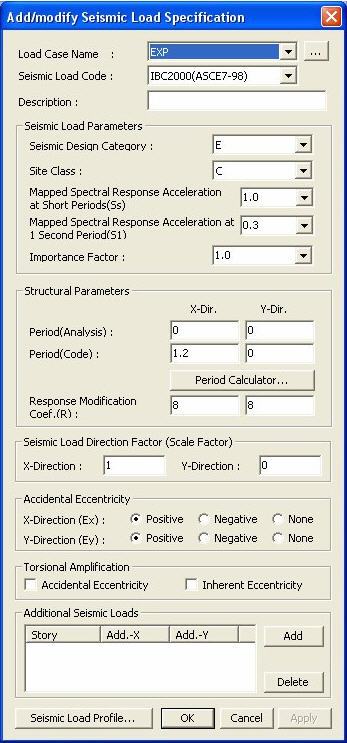
Access Seismic Loads to activate the dialog
box defining the seismic loads. Click
Add/Modify Seismic Load Design Code dialog box
|
 to auto-generate the data necessary for
the stories and the application of seismic loading.
to auto-generate the data necessary for
the stories and the application of seismic loading.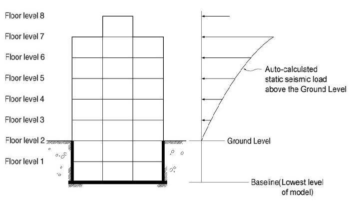
|
Damping (%) |
0 |
2 |
5 |
7 |
10 |
15 |
20 |
25 |
30 |
|
Damp |
3.20 |
1.40 |
1.00 |
0.90 |
0.80 |
0.70 |
0.60 |
0.55 |
0.50 |
Seismic Zone (Z)
Seismic Zone Related Data
General Zone
Horizontal Spectral Accel.
Short Period (Ss): Horizontal Spectral Acceleration at short periods
1 Sec Period (S1): Horizontal Spectral Acceleration at 1 second periods
Site Magnify Factor
Soil Type
Short Period (Fa): Site Magnify Factor at short periods
1 Sec Period (Fv): Site Magnify Factor at 1 second periods
Near Fault Zone
Horizontal Spectral Accel.
Short Period (Ss): Horizontal Spectral Acceleration at short periods
1 Sec Period (S1): Horizontal Spectral Acceleration at 1 second periods
Near Source Factor
Short Period (Na): Near Source Factor at short periods
1 Sec Period (Nv): Near Source Factor at 1 second periods
Site Magnify Factor
Soil Type
Short Period (Fa): Site Magnify Factor at short periods
1 Sec Period (Fv): Site Magnify Factor at 1 second periods
Taipei Basin
Sub Zone
Horizontal Spectral Accel.
Short Period (Ss): Horizontal Spectral Acceleration at short periods
Trans. Period: Transfer period
T0: S1/Ss
Importance Factor(I)
Seismic Magnify Factor
Seismic Zone (Z)
Soil Type
Importance Factor (I)
Seismic Magnifying Factor
(available upon request)
Seismic Zone Factor (Z)
Soil Period (Tc)
Std. Base Shear Factor (C0)
Seismic Base Shear Distribution Factor (Ai)
Note
Ai is automatically calculated or entered by the user.
Design Spectral Response Acceleration
Seismic Zone
Site Class
Sds: Spectral response acceleration at short periods
Sd1: Spectral response acceleration at a period of 1 sec
Seis. Use Group
City Plan Region
Importance(Ie)
Seis. Design Category
Soil Profile Type
Earthquake Zone
Importance Factor
Soil Profile Type
Earthquake Zone
Importance Factor
Seis. Fortification Intensity
Site Class
Structure Type
Damping ratio
Frequent Earthquake
Scarce Earthquake
Masonry Multistory, Framed 1st Story, Interior Frame - Exterior Masonry Structure
Near Source Category
Seis. Fortification Intensity
Site Class
Structure Type
Damping Ratio
Frequent Earthquake
Scarce Earthquake
Masonry Multistory, Framed 1st Story, Interior Frame - Exterior Masonry Structure
 Structural Parameters
Enter the parameters defining the characteristics of the structure.
Period (Analysis): Obtained by eigenvalue analysis
Period (Codr): Obtained by the Code method
Response Modification Coefficient (R)
Period: Periods of the structure calculated from the equation in the code
Ductility Coefficient (R): Numerical coefficients representative of the inherent overstrength and global ductility capacity of a lateral force resisting system
Period (Analysis): Natural periods of the structure from eigenvalue analysis
Period (Code): Natural periods of the structure calculated from the equations in the code
Ductility Coefficient (Rw): Numerical coefficients representative of the inherent overstrength and global ductility capacity of a lateral force resisting system
Period (Analysis): Natural periods of the structure from eigenvalue analysis
Period (Code): Natural periods of the structure calculated from the equations in the code
Response Modification Coeff.
Period (Analysis): Natural periods of the structure from eigenvalue analysis
Period (Code): Natural periods of the structure calculated from the equations in the code
Response Modification Factor (R)
 : Auto-calculation of periods from the code equations
N: Number of Stories
H: Height of the building
Ds: Length of the wall or braced frame which constitutes the main lateral-force-resisting system in the direction parallel to the
applied forces
Note
If the main lateral-force-resisting system does not have a well-defined
length then D Shall be used in lieu of Ds
D: Length of the
building in a direction parallel to the applied forces
Fundamental Period
: Auto-calculation of periods from the code equations
H: Height of the building
Ac: Combined effective area of the shear walls in the first story of building
d: lateral displacement if the top of the building due to the gravity loads applied horizontally
Fundamental Period
: Auto-calculation of periods
from the code equations
h: Height of the building (unit: m)
d: Width of the building in a direction parallel to the seismic load at the 1st floor
Response Reduction Factor
Analytical Period: Natural periods of the structure from Eigenvalue analysis
Approximate Period: Natural periods of the structure calculated from the equations in the code
Fundamental Period
Response Modification Factor
Analytical Period: Natural periods of the structure from Eigenvalue analysis
Approximate Period: Natural periods of the structure calculated from the equations in the code
Response Modification Factor
(available upon request)
Period (T)
Period Calculator
Analytical Period: Natural periods of the structure from Eigenvalue analysis
Approximate Period: Natural periods of the structure calculated from the equations in the code
 : Auto-calculation of periods from the code equations
Fundamental Period
Response Modification Factor
Period (Analysis): Natural periods of the structure from eigenvalue analysis
Period (Code): Natural periods of the structure calculated from the equations in the code
: Auto-calculation of periods
from the code equations
Response Modification Coeff.
Period (Analysis): Natural periods of the structure from eigenvalue analysis
Period (Code): Natural periods of the structure calculated from the equations in the code
: Auto-calculation of periods
from the code equations
Response Modification Coeff.
Fundamental Period
: Auto-calculation of periods from the code equations
H: Height of the building
Bx: Width of building subjected to seismic load in the Global X-axis direction
By: Width of building subjected to seismic load in the Global Y-axis direction
n: Number of Stories
Fundamental Period
: Auto-calculation of periods from the code equations
H: Height of the building
Bx: Width of building subjected to seismic load in the Global X-axis direction
By: Width of building subjected to seismic load in the Global Y-axis direction
n: Number of Stories
Seismic Load Direction Factor
Enter the directions and magnitudes of the seismic loads to be applied.
Scale Factor in Global X: Scale factor in GCS X-direction
Scale Factor in Global Y: Scale factor in GCS Y-direction
Eccentricity Direction
Assign the directions to be considered with accidental eccentricities in the structure.
If the 'None' option is selected, accidental eccentricity is not considered.
Torsional Amplification
Accidental Eccentricity: Check whether or not to apply amplification to torsion due to Accidental Eccentricity.
Inherent Eccentricity: Check whether or not to apply amplification to torsion due to the eccentricity between the center of mass and the center of stiffness of the building structure.
Additional Seismic Loads
Enter additional seismic loads that the auto-calculation does not take into account
Press  to enter the stories
to apply additional seismic loads and the magnitudes for each direction.
to enter the stories
to apply additional seismic loads and the magnitudes for each direction.
 : Display Tables and Graphs
in a spreadsheet form for each loading direction and component of the
auto-calculated seismic load.
: Display Tables and Graphs
in a spreadsheet form for each loading direction and component of the
auto-calculated seismic load.
Component: Assign the seismic loading direction for a graphic display
Select Profile: Select the items to be displayed
Story Force
Story Shear
Overturning Moment
 : Display a spreadsheet Text
Output file showing the seismic load calculation process. Text
: Display a spreadsheet Text
Output file showing the seismic load calculation process. Text
Editor is automatically executed.
 : Apply the auto-calculated
equivalent static seismic loads to the model.
: Apply the auto-calculated
equivalent static seismic loads to the model.
Note
Refer to the relevant code for details regarding the equivalent seismic
load calculation.