Displacement Participation Factor
| ||||||||||||||
|
| ||||||||||||||
|
| ||||||||||||||
|
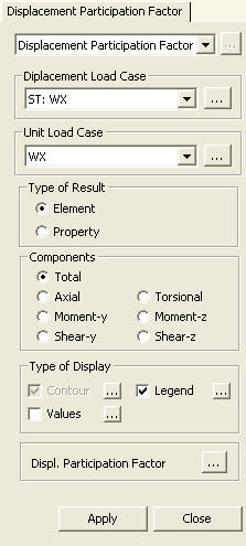
Based on a lateral load case, displacement participation by each element for each force component (Axial, Torsional, Moment-y, Moment-z, Shear-y & Shear-z) can be checked in Contour and Value. In order to check the displacement participation factor, a unit load needs to be input in the direction of the lateral load at the location of the maximum displacement. | ||||||||||||||
|
| ||||||||||||||
|
| ||||||||||||||
|
| ||||||||||||||
|
From the Main Menu select Results > Displacement Participation Factor.
Select Results > Displacement Participation Factor in the Menu tab of the Tree Menu. | ||||||||||||||
|
| ||||||||||||||
|
| ||||||||||||||
|
Let us take an example of a simply supported beam, which exhibits a deflection of Δ under the external load L (Fig. 1a). We then apply a unit load at the location of Δ (Fig. 1b) in the same direction of Δ
Fig. 1 Unit load method
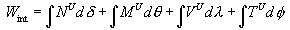
The external virtual work (
The deflection Δ due to the external load
L in Fig. 1a can be expanded into axial deformation
If the above beam behaves linearly, and we
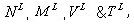
define the internal forces caused by the external load L as
We
then apply the principle of virtual work, (
where,
Expanding the concept of the unit load method
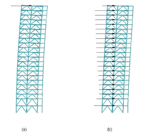
to a building subject to a wind load as shown in Fig. 2b, we apply a unit
load at the top of the building as Fig. 2a to find the maximum lateral
displacement. If we consider the maximum displacement due to the wind
as a virtual displacement
where, m : Number of elements
Displacement participation in a lateral resisting system can be quantified and as such it can be optimized.
Fig. 2 Unit load application for lateral displacement calculation
|


 : Displacement
participation by each element
: Displacement
participation by each element  :
Each displacement component of each element
:
Each displacement component of each element  : Weight
of each element
: Weight
of each element 
 : Displacement
participation by each section property
: Displacement
participation by each section property 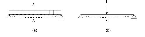
 ) in Fig. 1b is expressed as
 ,
flexural deformation
,
flexural deformation  , shear deformation
  and
torsional deformation
and
torsional deformation  . And the internal force in the simple
beam due to the unit load is consisted of
. And the internal force in the simple
beam due to the unit load is consisted of 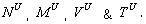 . The internal
virtual work done by the unit load to cause the deformation Δ becomes
. The internal
virtual work done by the unit load to cause the deformation Δ becomes
 , the deformation of the beam element becomes
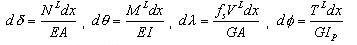
 ), to derive
the equation of the unit-load method.
), to derive
the equation of the unit-load method. 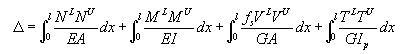
 : shape factor for shear
  is the sum of displacements contributed
by the individual elements.
is the sum of displacements contributed
by the individual elements. 
 is
said to be the displacement participation of each element, which is expressed
as
is
said to be the displacement participation of each element, which is expressed
as 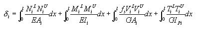
|
Contour |
Display the displacement participation of the model in contour. |
|
|
Ranges: Define the contour ranges.
Note If the Contour Range values exceed the output values, they are entered at Rank 0 and Rank 11.
Number of
Colors: Assign the number of colors to be included in the contour
(select among 6, 12, 18, 24 colors) Colors: Assign or control the colors of the displacement contour.
Color Table: Assign the type of Colors.
Reverse Contour: Check on to reverse the sequence of color variation in the contour.
Contour Line: Assign the boundary line color of the contour
Element
Edge: Assign the color of element edges while displaying the contour Contour Options: Specify options for contour representation
Contour Fill
Gradient
Fill: Display color gradient (shading) in the contour.
Draw Contour
Line Only
Mono line: Display the boundaries of the contour in a mono color.
Contour
Annotation
Spacing: Display the spacing for the legnd or annotation.
Coarse Contour
(faster) (for large plate or solid
model)
Extrude |
 : Assign the color distribution
range of contour. Using the function, specific colors for specific ranges
can be assigned.
: Assign the color distribution
range of contour. Using the function, specific colors for specific ranges
can be assigned. : Control the colors by zones
in the contour.
: Control the colors by zones
in the contour.|
Values |
Display the nodal displacements in numerical values. The font and color of the numbers can be
controlled in |
|
|
Decimal
Points: Assign decimal points for the displayed numbers Min &
Max: Display the maximum and minimum values Set Orientation: Display orientation of numerical values
Note |

|
Legend |
Display various references related to analysis results to the right or left of the working window.
Element numbers pertaining to the maximum and minimum forces are displayed. |
|
|
Legend Position: Position of the legend in the display window
Rank Value Type: Values for Legend (Exponential or fixed values) |
 Type
of Display
Type
of Display
Click the Displ. Participation Factor button to prompt a dialog box, which shows the prediction of lateral displacement and the change of weights based on changing sections.
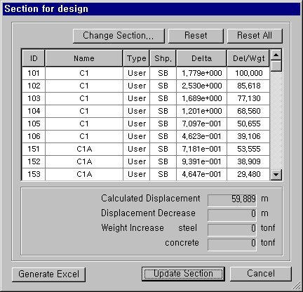
Section for Design dialog box
 : Used to change sections
selected in the list
: Used to change sections
selected in the list
 : Used to revert sections
selected in the list to the sections of the original model
: Used to revert sections
selected in the list to the sections of the original model
 : Used to revert all the changed
sections to the sections of the original model
: Used to revert all the changed
sections to the sections of the original model
Calculated Displacement: Lateral displacement
Displacement Decrease: Change (reduction) of displacement
Weight Increase steel: Increase in weight of structural steel
concrete: Increase in weight of concrete
 : Incorporate the changed
sections into the model.
: Incorporate the changed
sections into the model.