Grid Mesh
Grid Mesh is used to generate mesh for orthogonal geometrical entities, quadrilaterals and/or triangles using quadrilateral and triangular elements. The feature does not support Polygons (more than 5 edges), Circle(s) and Arc(s).
Applicable Modules:
Ground
|
Slope |
Soft Ground |
Foundation |
Seepage |
Dynamic |
From
the Main
Menu, select Model
> Mesh > Grid Mesh ![]()
From the Command Line, type 'GridMesh' or 'GRM'
Select Object
Select the objects to be meshed.
Surface
Select surface(s) to be meshed.
Map Mesh Area
Select domains enclosed by lines to be map meshed.
Select Surface(s)
Select the surfaces to be map meshed (In case object selection is Surface).
Mesh Size
Element Size
Enter the desired element size.
Ground Material Property
Select
a Ground
Material Property to be assigned to the mesh. Click ![]() to the right to Add new, Modify or Delete Ground Material Property.
to the right to Add new, Modify or Delete Ground Material Property.
Mesh Set
Enter the name of the Mesh Set.
Create new Mesh Set if same name exists
Check on ![]() to create a new Mesh Set if a Mesh Set
with the same name exists.
to create a new Mesh Set if a Mesh Set
with the same name exists.
Trapezoidal pattern permitted
Check on ![]() the option to allow trapezoidal shape elements when generating
elements at slopes of enclosed domains.
the option to allow trapezoidal shape elements when generating
elements at slopes of enclosed domains.
Generate Higher Order Elements
Check on to generate higher order elements with intermittent nodes.
Use the Material assigned to Surface
Generates mesh elements with same Ground Material Property as that of the source Surface.
![]() Click to generate mesh. The dialog box will close automatically.
Click to generate mesh. The dialog box will close automatically.
Press the ESC
key or click ![]() to close
the dialog box.
to close
the dialog box.
![]() After mesh is generated, work process will switch to the state
of Select Surface(s)/Curve(s) upon clicking.
After mesh is generated, work process will switch to the state
of Select Surface(s)/Curve(s) upon clicking.
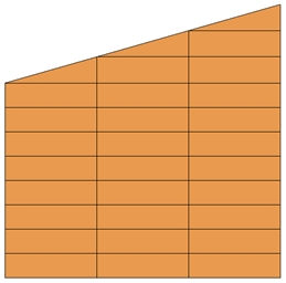
Note:
When
Trapezoidal Shape Permitted is checked on ![]() , vertical lines are drawn irrespective of the connectivity of
the horizontal lines and the sloped side. Vertical and horizontal
lines are created at uniform spacing in generating elements. The
elements at the sloped side are generated in the shapes of triangles
and trapezoids as shown below:
, vertical lines are drawn irrespective of the connectivity of
the horizontal lines and the sloped side. Vertical and horizontal
lines are created at uniform spacing in generating elements. The
elements at the sloped side are generated in the shapes of triangles
and trapezoids as shown below:
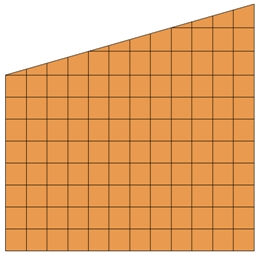
If the option is unchecked, vertical lines are created only where the horizontal lines meet the sloped side. Therefore, the division of a domain is controlled by the criterion generating only triangular elements at the slope side as shown below: