Define the plastic hinge data to be used in Pushover analysis.
Note
Hinge properties such as
yield strength are calculated based on the specified design code in Design>Concrete/Steel
Design Parameter>Design code.
From the Main
Menu selectDesign > Pushover Analysis
> Define Hinge
Properties
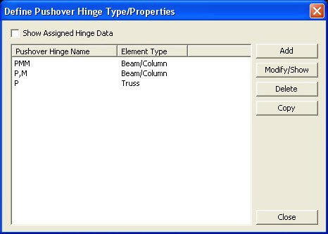
Define
Pushover Hinge Data dialog box
Click the button to define
plastic hinge information in the dialog box below. Click the button to confirm or modify and the button
to delete the data entry. Select the pushover hinge to be copied in the
dialog box and click button.
After defining the hinge type and assigning
it to the selected members, check on the Show Generated Hinges in the
Define Pushover Hinge Data dialog box to check the automatically calculated
hinge data by the section information. Select the hinge data to be checked
and click the button to prompt the Add/Modify Hinge Data
Type dialog box in which the button is clicked to check
the hinge data. Corrections to the assigned hinge data are not permitted
here.
Note 1
When members are assigned hinge properties,
inherent titles are assigned to the automatically generated hinge data.
For example, "B1-PMM" represents:
B: Hinge assigned to a beam element
1: Sequential number assigned to by element
types
Beam: Assigned hinge type (Beam, Column, PMM…)
Note 2
Hinge
properties of each element are automatically generated according to the
sectional information. For reinforced concrete members, reinforcing steel
must be pre-determined through the design feature in Gen. Reinforcing
steel data for the relevant sections must be provided in Modify Beam (Column,
Brace & Wall) Section Data ofConcrete
Design Parameter. If the automatic design
feature for reinforced concrete members (Concrete
Code Design) is used, you are required
to enter the reinforcing data using the button in the Design
Result dialog box for each element.
Note 3
Strength calculation method for Value Type
Steel Section
1. Sectional information such as Area, Asy,
Asz, Cym, Cyp, Czm, Czp, Zyy, and Zzz cannot be 0 for auto-calculation
(Zyy,
Zzz are new items added in Value Type and can be checked in Model >
property > Section).
2. Hinge strength is calculated for P, My-Mz,
Vy-Vz, and PMM.
3. For Yielding, the PM-Curve is generated
on the basis of Pc (compressive strength), Pt (tensile strength), and
M0 (flexural
strength
at P=0, or Fy×yy, Fy×zz).
4. For Ultimate, the PM-Curve is generated
on the basis of Pc (compressive strength), Pt (tensile strength), and
M0 (flexural
strength
at P=0, or Fy×Zyy, Fy×zz).
Add/Modify
Hinge Data Type dialog box
Hinge Properties Type Name
Define names of plastic hinge properties.
Description
State a brief description related to the
pushover hinge properties.
Element Type
Specify the type of element.
Beam/Column
: Beam or Column element
Wall
: Wall element
Truss
: Truss element
General
Link : Spring which can be defined at Model>Boundaries>Define
General Link Properties
Wall Type
Specify the type of wall element.
Membrane
: Only in-plane plasticity is considered
Plate : Both in-plane and out-of-plane
plasticity are considered
Material Type
Specify the type of material used to the
corresponding element.
Specify the load-deformation relationship
of the flexural member.
Moment-Rotation
(M-θ)
Moment-Curvature
(M-φ Lumped)
Moment-Curvature
(M-φ Distributed)
Pier Type
: For vertical members in the masonry material type. Hinge properties
are defined in terms of moment-rotation
relationship for a member’s section.
Spandrel
Type : For horizontal members in the masonry material type. Hinge
properties are defined in terms of moment-
rotation relationship for a member’s
section.
Interaction Type
None
: Axial force and biaxial moments are uncoupled from each other.
P-M-M in
Status Determination : Coupled axial force-biaxial moment behavior
is reflected by calculating the flexural yield strength of a hinge considering
the effect of axial force.
Component Properties
Fx, Fy,
Fz, Mx, My, Mz : Check on the degree of freedom to be assigned
to the plastic hinge type.
Hinge Location
: Specify the hinge location within the corresponding element.
Number of
Section : Specify the number of integration points when Definition
is selected as 'Moment-Curvature (M-φ Distributed)'.
Skeleton Curve : Specify the skeleton curve.
Note 1
The skeleton curves available
are as follows:
1. Bilinear Type (or Slip
Bilinear Type)
2. Trilinear Type (or Slip
Trilinear Type).
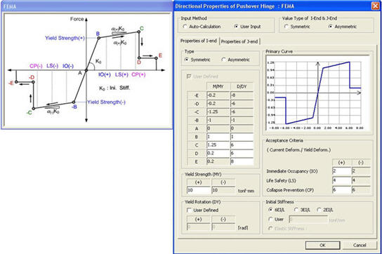
3. FEMA Type
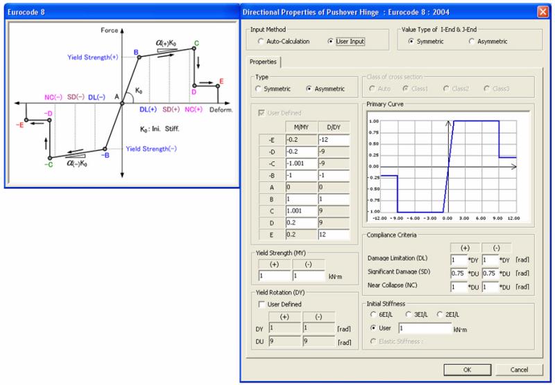
4. Eurocode8:2004
Slip Bilinear Type or Slip
Trilinear Type is activated when the Element Type is defined as 'Truss'
or 'General Link'.
Note 2
The
Multi-Linear Type is applicable for both the load control and the displacement
control methods and both FEMA and Eurocode 8 type is applicable only for
the displacement control method.
Enter the relevant hinge properties in the
following dialog box:
Hinge Property Data dialog box (Multi-Linear Type)
Input Method
Auto-Calculation
: The corresponding yield strength
is automatically calculated based on the design code.
Note
Following definitions are required for Auto-Calculation.
1. Design Code
2. Material and section properties defined
from the standards
3. Rebar data for RC members
User Input
: All the input
data are user-defined parameters.
Input Type
Strength - Stiffness Reduction Ratio : Define the Skeleton Curve using the yield
strength and the stiffness reduction ratio.
Strength
- Yield Deformation :
Define the Skeleton
Curve using the yield strength and the yield deformation defined by the
user.
Note
1. Strength - Yield Deformation
option is activated when the Input Method is set to User Input.
2.
Yield Deformation is changed depending on the component. (Fx : yield deformation,
Fy & Fz : yield strain, Mx & My & Mz : yield rotation angle)
Value Type of I-End &
J-End
Symmetric
: Select if rebar arrangement between i-end and j-end are symmetrical.
Asymmetric : Select if rebar arrangement
between i-end and j-end are asymmetrical.
Note
Value
Type of I-End & J-End option is activated when the hinge type is defined
as Moment-Rotation (M-Θ) or Moment-Curvature (M-φ Lumped) and User Input
option is selected. The asymmetrical yield strengths between I-end and
J-end are automatically reflected when input method is set to Auto-Calculation.
Type
Symmetric :
Select if the hinge properties are symmetric in the positive and negative
directions.
Asymmetric
: Select if
the hinge properties are asymmetric in the positive and negative directions.
Yield Strength
The
values are automatically calculated using the section information if Input
Method is set to Auto-Calculation. Or the user may enter the values of
Yield Moment and Yield Rotation manually if Input Method is User-Input.
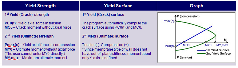
P1: 1st
Yield Strength
It
represents the cracking strength of concrete or the member force of a
structural steel member at the time the top or bottom fiber starts yielding.
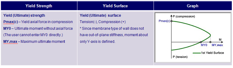
P2: 2nd
Yield Strength
It
represents the starting point of concrete rupture or yielding of reinforcing
steel. In the case of structural steel, it represents the
member
force at which an entire member starts yielding.
Note
The values
for the 2nd My must be greater than those for the 1st My (Mcr).
Stiffness Reduction Ratio
Use Value of Global Control Data : Stiffness reduction ratio defined in Pushover Global Control
dialog is used.
User Defined : User
defined stiffness reduction ratio is used.
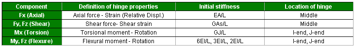
Initial Stiffness
6EI/L,
3EI/L, 2EI/L : It is activated when Definition is defined as Moment
- Rotation (M-θ).
User
: Defined by the user
Elastic
Stiffness:Elastic
stiffness is used for the initial stiffness.
Initial Gap
Enter
the initial gap in tension and compression when element type is Truss
or General Link for the Slip Bilinear Type or Slip Trilinear Type of skeleton
curve.
Auto-Calculation :
The corresponding yield strength is automatically calculated based on
the design code.
Note
Following definitions are required for
Auto-Calculation.
1. Design Code
2. Material and section properties defined
from the standards
3. Rebar data for RC members
User Input
: All the input data are user-defined parameters.
Value Type of I-End &
J-End
Symmetric
: Select if rebar arrangement between i-end and j-end are symmetrical.
Asymmetric :
Select if rebar arrangement between i-end and j-end are asymmetrical.
Note
Value
Type of I-End & J-End option is activated when the hinge type is defined
as Moment-Rotation (M-Θ) or Moment-Curvature (M-φ Lumped) and User Input
option is selected. The asymmetrical yield strengths between I-end and
J-end are automatically reflected when input method is set to Auto-Calculation.
Type
Symmetric :
Select if the hinge properties are symmetric in the positive and negative
directions.
Asymmetric :
Select if the hinge properties are asymmetric in the positive and negative
directions.
Yield Strength (MY)
The
values are automatically calculated using the section information if Input
Method is set to Auto-Calculation. Or the user may enter the values of
Yield Moment manually if Input Method is set to User-Input. The coordinate
system follows the Element local Coordinate System.
Yield Rotation (DY)
User Defined
The
values are automatically calculated using the section information if this
option is checked off. Or the user may enter the values of Yield Rotation
manually. The coordinate system follows the Element local Coordinate System.
Enter
the target performance indices for the structure in terms of ductility
(Total Deformation/Yield Deformation). The values outlined in FEMA-273
are used as the reference values. Only positive values are entered if
the case is symmetrical.
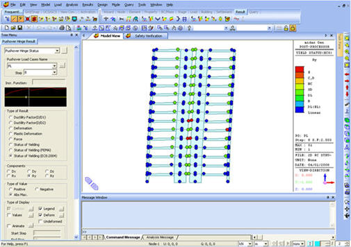
Note
The legend identifying the status of hinge
formation reflects the Acceptance Criteria after pushover analysis is
completed. Select Hinge Status in Type of Display in Deformed Shape to
observe the status of hinge formation by incremental steps.
Initial Stiffness
6EI/L, 3EI/L, 2EI/L :
It is activated when Definition is defined as Moment - Rotation (M-θ).
User :
Defined by the user
Elastic
Stiffness:Elastic
stiffness is used for the initial stiffness.
The Yield Surface Properties button enables
us to define the interaction of axial force and bending moments where
P-M-M in Status Determination of interaction type is selected.
Hinge Property Data dialog box (Eurocode 8: 2004 Type)
Input Method
Auto-Calculation :
The corresponding yield strength is automatically calculated based on
the design code.
Note
Following definitions are required for
Auto-Calculation.
1. Design Code
2. Material and section properties defined
from the standards
3. Rebar data for RC members
User Input
: All the input data are user-defined parameters.
Value Type of I-End &
J-End
Symmetric
: Select if rebar arrangement between i-end and j-end are symmetrical.
Asymmetric :
Select if rebar arrangement between i-end and j-end are asymmetrical.
Note
Value
Type of I-End & J-End option is activated when the hinge type is defined
as Moment-Rotation (M-Θ) or Moment-Curvature (M-φ Lumped) and User Input
option is selected. The asymmetrical yield strengths between I-end and
J-end are automatically reflected when input method is set to Auto-Calculation.
Type
Symmetric :
Select if the hinge properties are symmetric in the positive and negative
directions.
Asymmetric :
Select if the hinge properties are asymmetric in the positive and negative
directions.
Yield Strength (MY)
The
values are automatically calculated using the section information if Input
Method is set to Auto-Calculation. Or the user may enter the values of
Yield Moment manually if Input Method is set to User-Input. The coordinate
system follows the Element local Coordinate System.
Yield Rotation (DY)
User Defined
The
values are automatically calculated using the section information if this
option is checked off. Or the user may enter the values of Yield Rotation
manually. The coordinate system follows the Element local Coordinate System.
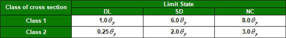
Class of Cross Section
Rotation capacity at the end of steel beams
or columns depends on the class of cross section. In order for the program
to automatically determine the class of cross section for the pushover
analysis, select ‘Auto’. For the automatic classification Steel
Code Checking should be performed first.
Compliance Criteria
Enter
the target performance indices for the structure in terms of deformation.
The values outlined in Eurocode 8-3 are used as the basic values. Only
positive values are entered if symmetrical.
Note
The legend identifying the status of hinge
formation reflects the Compliance Criteria after pushover analysis is
completed.
Initial Stiffness
By default, initial stiffness of moment
hinge is taken equal to the Yield Strength divided by Yield Rotation,
and the Yield Strength and Yield Rotation are automatically calculated
based on Eurocode 8 part 1 & 3. Any safety factors including partial
factors are not reflected in the calculation of strength and deformation.
6EI/L, 3EI/L, 2EI/L :
It is activated when Definition is defined as Moment - Rotation (M-θ).
User :
The initial stiffness that has been automatically calculated is displayed
here. If the value is
modified,
the modified value will be applied as the initial stiffness.
Elastic
Stiffness:Elastic
stiffness is used for the initial stiffness.
The Yield Surface Properties button enables
us to define the interaction of axial force and bending moments where
P-M-M in Status Determination of interaction type is selected.
User
: All the input data are user-defined parameters.
Auto : The corresponding yield
strength is automatically calculated based on the design code.
Value Type of I-End &
J-End
Symmetric
: Select if rebar arrangement between i-end and j-end are symmetrical.
Asymmetric
: Select if rebar arrangement between i-end and j-end are asymmetrical.
Note
Value
Type of I-End & J-End option is activated when the hinge type is defined
as Moment-Rotation (M-Θ) or Moment-Curvature (M-φ Lumped) and User Input
option is selected. The asymmetrical yield strengths between I-end and
J-end are automatically reflected when input method is set to Auto-Calculation.
Type (Y-Axis, Z-Axis)
Symmetric :
Select if the hinge properties in Y-axis and Z-axis are symmetrical.
Asymmetric
: Select if
the hinge properties in Y-axis and Z-axis are asymmetrical.
Component Properties
Define the skeleton curve and
initial stiffness, etc for the rotation about y-axis and z-axis.
Type (Plus, Minus)
Symmetric :
Select if the hinge properties in the positive and negative moment are
symmetrical.
Asymmetric
: Select if the hinge properties in the positive and negative moment are
asymmetrical.
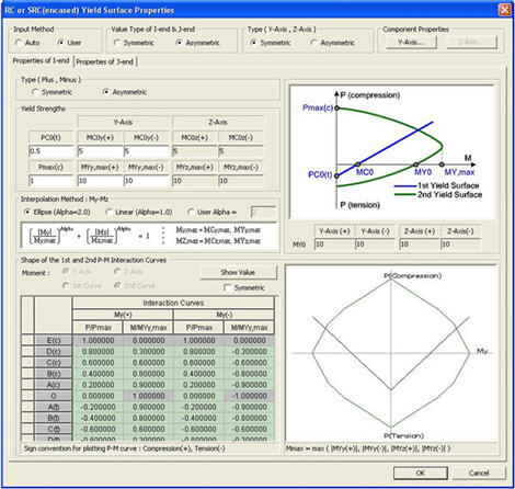
Yield Strengths
Yield
strength about y-axis and z-axis are automatically calculated using the
section information if Input Method is set to Auto. Or the user may enter
the values of Yield Moment manually if Input Method is set to User.
Interpolation Method :
My-Mz
PM interaction curve is interpolated by
the Bresler's Load Contour Method. The curve may be of elliptic, linear
or user-defined shape. The values of Alpha, 1 and 2 represent linear and
elliptic shapes respectively.
Note
If
the User defines the interpolation method, the bi-axial moment is formulated
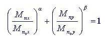
by the Bresler's Load Contour Method. In a 3-dimentional interaction diagram,
the curve on a Mx-My plane passing a given Pn is represented by the expression
If is assumed, the expression becomes,
In general, retains a value
in the range of 1.0-2.0 in a rectangular section. If is
set at 1.0, the curve becomes a straight line and as such it produces
the most conservative design. The value of 1.5 may result in a close approximation.
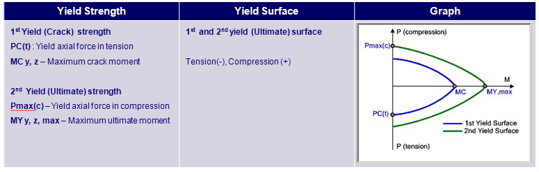
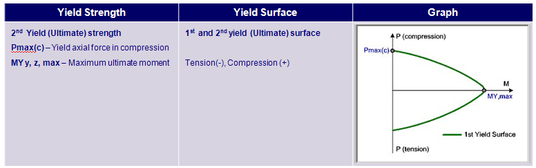
Shape of the 1st
and 2nd P-M Interaction Curves
Yield surface about strong
and weak axes can be checked by table or graph.
Show
Value : Click to display the applied forces and moments in analysis.
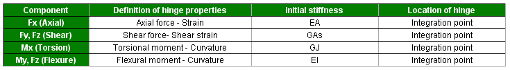
2. When Definition is Moment-Curvature
(M-φ Lumped, Distributed)
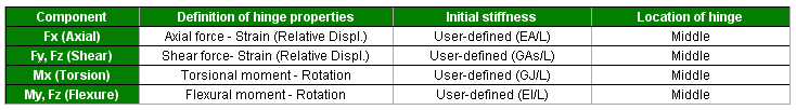
3. When Element Type is Truss
(Fx component):
4. When Element Type is General
Link
Masonry Properties
In the structural model, masonry spandrels
may be taken into account as coupling beams between two wall elements.
This assumption implies that they should regularly bonded to the adjoining
walls and connected both to the floor tie beam and to the lintel below.
If the structural model takes into account the coupling beams, a frame
analysis may be used for the determination of the action effects on the
vertical and horizontal structural elements.
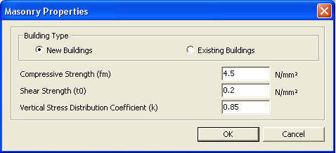
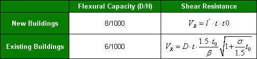
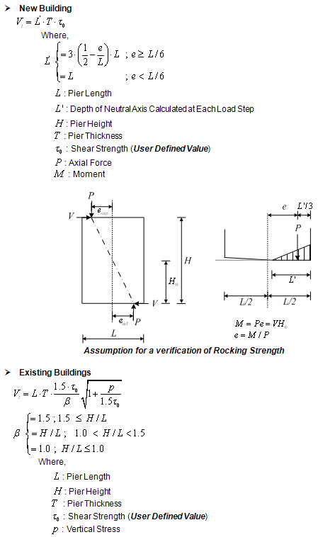
Building Type:
Flexural capacity and shear resistance of masonry pier depends on the
type of building as shown in the table below.
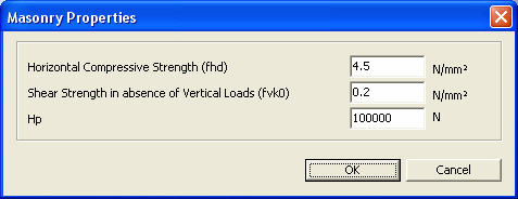
Following data are required
to calculate the resistance of masonry pier.
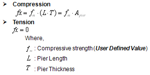
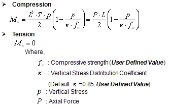
Compressive Strength (fm)
Shear Strength (t0)
Vertical Stress Distribution
Coefficient (k)
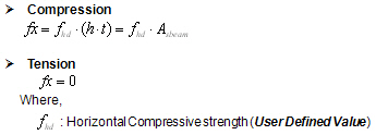
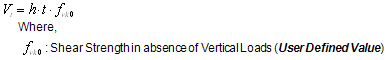
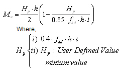
Note 1
How to calculate the resistance
- Axial resistance:
- Shear resistance:
- Flexural resistance
Note 2
Calculated
resistance can be checked in Design > Pushover Analysis > Pushover
Hinge Result Table >Beam Summary table.
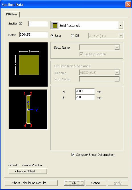
Note
3Element Local axis of masonry wall
pier
In-plane
horizontal direction and transverse direction of the wall pier should
coincide with the local z-axis and local y-axis of the element, respectively
as shown in the figure below, which directly affects the resistance of
the wall pier. Also, the program calculates hinge properties (My component)
on the assumption above.
 button to define
plastic hinge information in the dialog box below. Click the
button to define
plastic hinge information in the dialog box below. Click the button to confirm or modify and the
 button
to delete the data entry. Select the pushover hinge to be copied in the
dialog box and click
button
to delete the data entry. Select the pushover hinge to be copied in the
dialog box and click  button.
  button is clicked to check
the hinge data. Corrections to the assigned hinge data are not permitted
here.
button is clicked to check
the hinge data. Corrections to the assigned hinge data are not permitted
here. button in the Design
Result dialog box for each element.
button in the Design
Result dialog box for each element.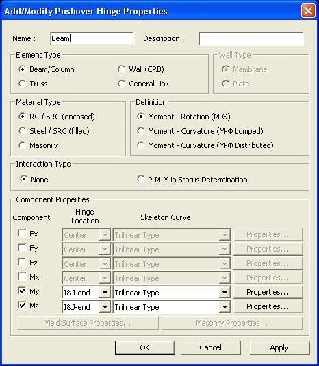
 Hinge Properties Type Name
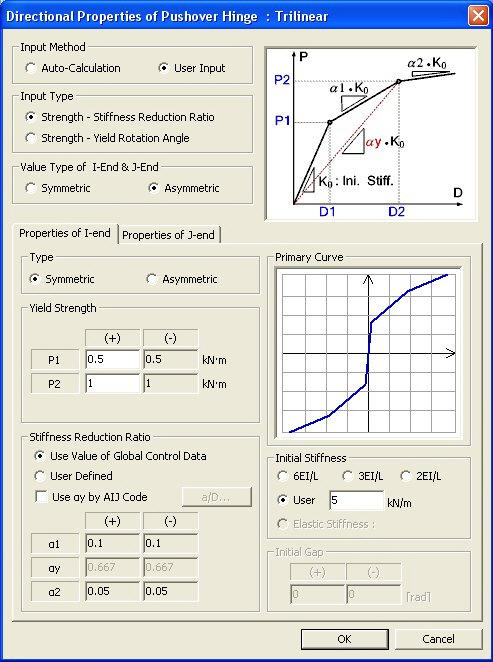
 Input Method
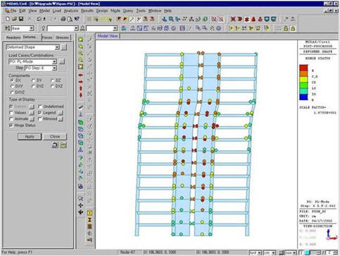


 is assumed, the expression becomes,
 retains a value
in the range of 1.0-2.0 in a rectangular section. If
retains a value
in the range of 1.0-2.0 in a rectangular section. If